The sense rods are analogous to the clock rods of the Digi-Comp I. It is the sense rods which examine the states of the bit assemblies and determine which actuator rods will operate during a given cycle by moving them from their normal rest positions.
There are two sense rods per control stage.
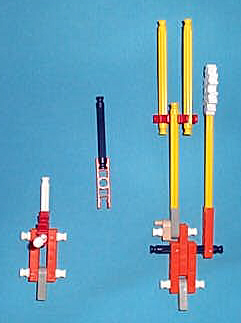
This picture shows the three subassemblies which form a sense rod.
The subassembly on the left is the bottom end of the sense rod. The subassembly in the middle of the picture is the part which engages with the red programming hardware of the bit assembly. Each sense rod has one of these for each bit of the knex-i-comp.
The subassembly on the right is the top part of the sense rod.
In the next picture, the sense rod is fully assembled.
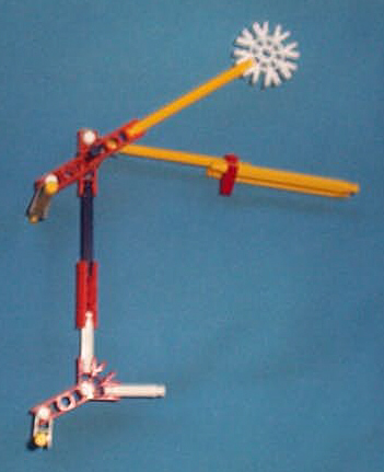
The white (arity 8) connector and yellow strut at the top form the sense rod weight, which ensures that the sense rod will drop and engage with the red programming hardware of the bit assembly when allowed to by the sense rod lifter.
The three yellow struts, red (arity 3) connector and gray (arity 1) connector form the control/actuator linkage , which engages with hardware at the top of the corresponding actuator rod to move the actuator rod off-normal when the sense rod lowers.
The sense rod moves up and down via a double hinged swinging arm composed of two orange (arity 2) connectors. One end of the arm is hinged through the center hole of one of the orange (arity 1) connectors of the sense rod proper. The other end is hinged by a white strut to a gray (arity 1) connector which is mounted vertically on the structural framework.
There are one orange (arity 2) connector and one blue strut per bit assembly. The blue strut will engage with the red (arity) 3 connectors of the programming hardware when the sense rod lowsers and the red connector is oriented horizontally.
The horizontal blue strut mounted at the bottom engages with the sense rod lifter during phases phase 3, phase 4, phase 5 and phase 6 of the operating cycle.