The Kraken Tentacle Targets
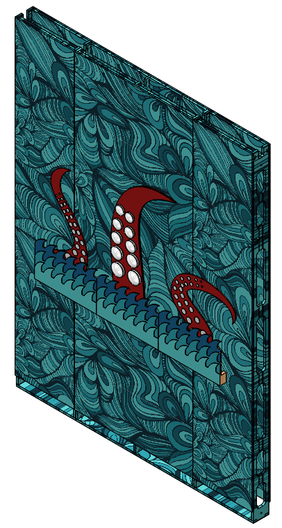
Players need targets to shoot at with the lightning cannon. Keeping with the themeing of this room, the targets for the players are moving tentacles representing Poseidon's Kraken monster. Static, 2.5D tentacles supplement the design of the room, as well, and are integrated into a marine scene with wave patterns and oceanic imagery. An example of one moving and two static targets integrated onto a wall section is shown below.
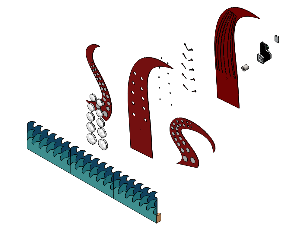
The targets must be about 3 to 4 feet off the ground to allow players to move under the net to collect balls, thus creating the illusion that the tentacles are bursting up from the water, placing the targets at about eye level. An exploded view of this assembly is depicted below. The moving target is connected to a stepper motor via an aluminum coupling, thus allowing precise control of the arm's position and speed; this allows for tunable game difficulty. The NEMA 23 stepper is controlled through a stepper motor controller board and microcontroller. Flexible, silicone "suckers" on the front of the tentacle are mounted to a cosmetic tentacle front plate, and holes cut out of this front plate allow LEDs mounted on the tentacle back plate to shine through and illuminate the clear silicone. Additionally, underneath each LED is a force sensitive resistor which has a variable resistance which decreases with increasing pressure. When a ball contacts one of the silicone pads, it depresses the FSR and creates a readable signal on the microcontroller.
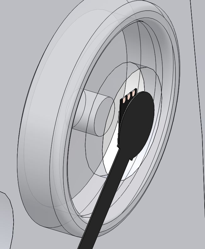
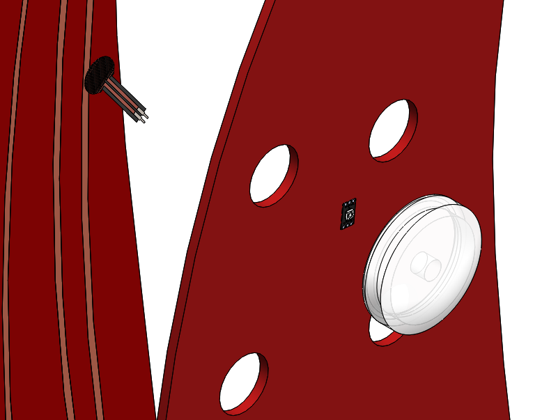
A more detailed view of the button assembly can be seen below. The silicone buttons each have a 1.2:1 size ratio to the next smallest button to give the illusion of an octopus tentacle. For purposes of the concept implementation, these buttons were cast in 3D printed molds, as these provided suitable surface finish quality and reproducability for the model. At low production volumes, this would be a suitable means to produce the buttons for a 5 Wits experience. Each button is cast with a small post in the middle which extends through the top sheet of the tentacle and rests just above the FSR. When the button is not depressed, it exerts no force on the FSR, but when the flexible silicon deforms when struck, it presses into the FSR and can be detected by the microcontroller. This feature is enlarged below.
This design features 10 FSRs under each silicone pad, and these resistors are connected in parallel such that when any experiences a decrease in resistance, it registers on the microcontroller. These resistors have 5V applied on one leg are then tied to ground with a 480 ohm pull-down resistor. The microcontroller reads the voltage on the low voltage bus connecting all the FSRs. This mechanism also allows a tunable "detection limit" to prevent players from just trying to hit the balls from the net into the tentacles; the programmer can increase the detection limit to a level where only the high force from the cannon-propelled ball will trigger detection.
For illumination, the design uses Adafruit RGB NeoPixels - individually addressable LEDS with a low profile and simple control. They are powered through the same 5V bus as the FSRs and are controlled through a single digital input pin. These specific LEDs allow simple control of the color, here purple for normal operation and red for a "hit detected" state, and also interesting patterns to be displayed. These LEDs, as well as all of the other electronics mounted on this tentacle backboard, are connected through copper tape circuitry. This copper tape allows an extremely low profile circuit design, thereby allowing the tentacle front and back boards to be mounted together with no interefering wires or components.

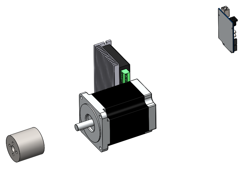
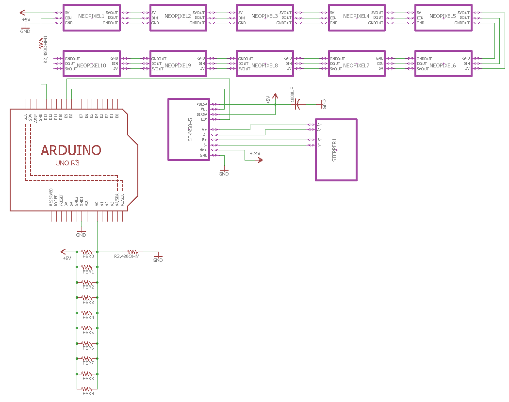
The mechanical actuation is done through a NEMA 23 stepper motor. This motor is mounted to the inside of the wall through screws through the motor housing, and mechanically drives the tentacle through an aluminum coupling. This motor requires a specific power demand supplied through a ST-M5045 micro-stepping stepper motor driver powered through a 24V, 10A power supply. This motor driver may be operated at the minimum output current, 1A, to drive the motor. The motor driver is driven from the microcontroller through 5V power and 2 signal pins. One pin, DIR, specifies the direction the motor will spin depending on if it is HIGH or LOW, whereas the PUL pin will rotate the motor one step when it receives a HIGH then LOW signal pulse. For purposes of the concept implementation, the chosen microcontroller was an Arduino, but the relative simplicity of the actuation could similarly be achieved by an ATtiny44, as each mechatronic arm requires 3 digital outputs an 1 analog input. A hit can then be communicated to the central, show microcontroller through a single digital pin to increment the players' score. The mechatronic components, as well as the overall concept implementation circuit diagram, are depicted below.
The final, front view of the assembly, as well as a video depicting the motion and the hit detection mechanism, are shown below.

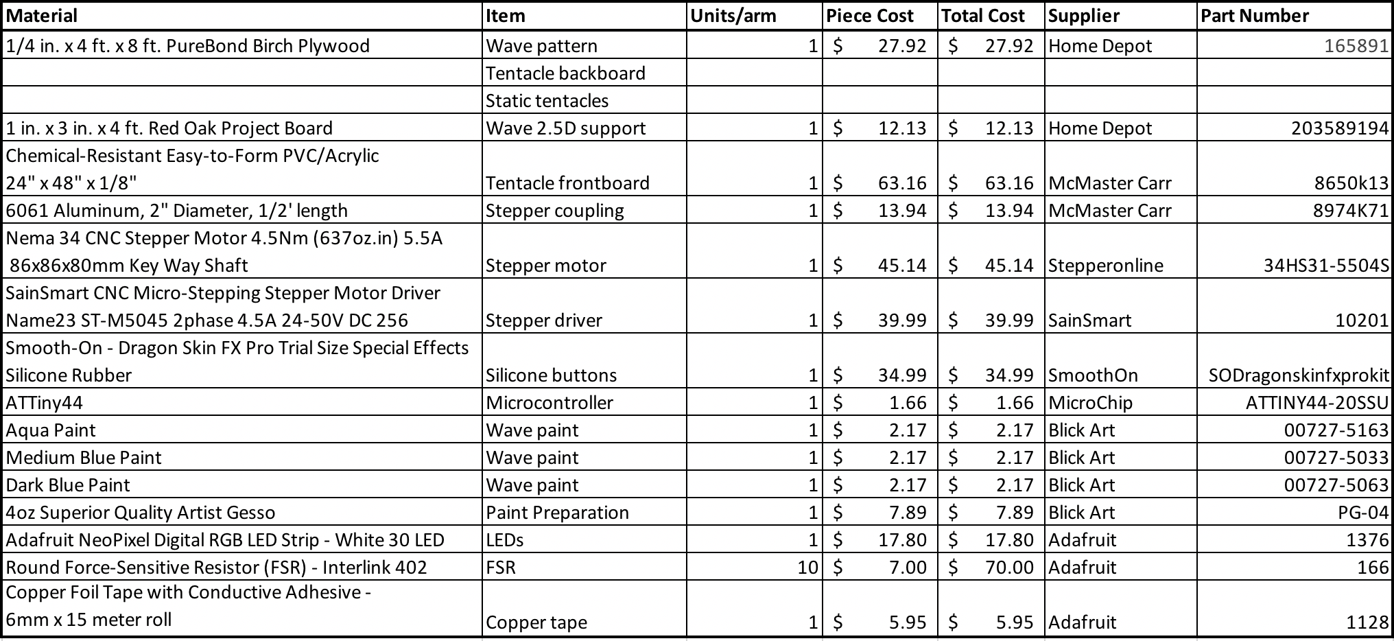
A full list of consumable materials for the fabrication of one rotating arm and two static arms is seen below in the BOM.