NOTE:with the new
development of
XCrySDen this document
has became a bit obsolete. Several new menu items were
added and a few were rearanged since this document was
written, nevertheless it should still be useful.
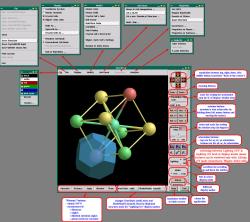
Below is a link to an interactive snapshot of
XCrySDen
main window with its menus as they appeared in an old
version 0.3. The appearence of the main window and
menus in the current version differs a bit,
nevertheless the snapshot is still useful. However, the
description of the menus that can be found here below
refers to the new version.
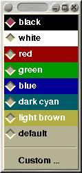
Changes the background color of render
window. Custom background color can be specified as
well (via
Custom ... entry).
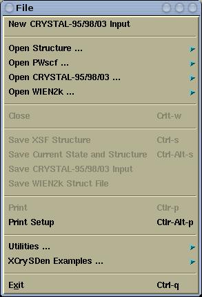
File menu has the followins items:
Creates new CRYSTAL-95/98/03 input file (just
standard geometry input and
geometry manipulation
keyword sections (refer to CRYSTAL-95/98/03 User
manual). User will be able to construct new structure
from scratch.
Molecular or crystalline structure will be read
from file and displayed. Here one can open the
following formats:
-
Crystalline structures files:
- XCrySDen files:
-
XSF (XCrySDen
Structure File)
-
AXSF (Animation
XCrySDen Structure File)
-
BXSF (i.e.
Fermi Surface Files)
- XCrySDen Scripting File
- PWSCF files:
- PWSCF Input File
- PWSCF Output File
- FHI98MD files:
- FHI98MD "inp.ini" File
- FHI98MD "coord.out" File
-
Molecular structure files:
- XYZ
- PDB
- Gaussian files:
- Gaussian Z-Matrix File
- Gaussian98 Output File
- Gaussian98 Cube File
Within this cascade menu, the
PWscf's
pw.x Input
and Output files can be opened.
Within this cascade menu, the CRYSTAL-95/98/03
input and properties files can be opened.
- by the ...Open
CRYSTAL-95/98/03 Input menu, the user
is able to manipulate standard geometry input and
geometry manipulation keyword sections (refer
to CRYSTAL-95/98/03 User manual) and render the
crystal (molecular) structure.
- the ... Open
Crystal-95/98/03 Properties menu reads
the
CRYSTAL's unit 9 (user specifies the
filename). User is able to render the following
properties:
- Band widths
- DOS and projected DOS
- band structure (prior to that user can
graphically select the k-path
- various 2D (isolines/colorplanes) and 3D
(isosurfaces) plots (charge density, charge
density difference, electrostatic potential)
This entry is related to WIEN2k GUI. User can
choose among:
-
Open WIEN2k Struct
File : displays crystal structure
from the struct file.
-
Render pre-Calculated
Density : reads struct,
output5 and rho files and renders
crystal structure and precomputed charge density.
-
Calculate & Render
Density : A 2D or 3D region for
charge density calculation can be interactively
selected by mouse-clicking. XCrySDen generates in5
file(s), calculates and renders charge density
either as isolines/colorplanes (2D) or isosurfaces
(3D).
-
Select
k-path : Reads struct file
and renders first Brillouin zone with special
k-points. K-path can be selected interactively by
mouse-clicking these points.
-
Fermi
Surface : trough a series of tasks
user is able to render the Fermi surface.
Closes the current case. Technically the current
XCrySDen
process is terminated and a new one is started.
Saves currently displayed structure in XSF format.
Saves currently displayed structure and large
number of the display parameters in
XCrySDen scripting file
format. Next time the script will be loaded (i.e. as
xcrysden -s script) the structure will be
displayed in the same way as it was saved, i.e., having
the same orientation, zoom, colors, and other display
parameters.
Read more ...
Saves currently displayed structure in the format
of CRYSTAL-95/98/03 input file (active only when used
as CRYSTAL96/98 GUI)
Saves currently displayed structure as WIEN2k
struct file.
Prints the currently displayed in EPS format.
Please take a look at this
hint for creating good quality
print-out.
Here the converting program for PPM to various
other graphics format (PNG,GIF,JPG) converion, together
with the command line options can be specified. The
convert program from the ImageMagick
program-package (
http://www.imagemagick.org/)
is a very convenient choice.
Read
More ...
Periodic Table of Elements can be found
here.
In this cascade menu one can found example files
included in the XCRYSDEN distribution for all supported
file formats.
Terminates the application.
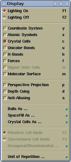
Display menu has the following items:
Toogles between lighting on and off mode
Toggles the display of XYZ Cartesian coordinate
system, which is rendered at the lower left corner of
the render window.
Toggles the display of atomic symbols.
Toggles the display of crystal cells (only for
periodic structures: polymers, slabs, crystals).
Toggles the display between the bonds that have
the same color as atoms and so-called
unicolor
bonds where all the bonds have the same color.
Toggles the display of H-bonds. See also the
Modify-->H-bonds
settings menu.
Toggles the display of forces, which are rendered
as vectors. The settings of the force display can be
done via
Modify-->Force
Settings menu.
Toggles the display of Wigner-Seitz cells. The
settings of the Wigner-Seitz cell display can be done
via
Modify-->Wigner-Seitz Cells
Settings menu.
Toggles the display of
Molecular surface.
The settings of the Molecular surface display can be
done via
Modify-->Molecular Surface
Settings menu.
Toggles between perspective and orthographic
projections.
Makes more distance object appear "darker" (or
more foggy). This effect produces more realistic
appearance of the scene. The depth-cuing can be
customized via the
Material/Fog/Antialias
Parameters menu.
The images displayed on the screen are aliased due
to final resolution of the screen (typically this is
75dpy). One can improve this aliasing by a technique
called anti-aliasing. It enhances the graphics quality.
Anti-aliasing is computationally very demanding, hence
it typical use is for printing, where it is very
useful, because it makes much superior print-out. The
anti-aliasing can be customized via the
Material/Fog/Antialias
Parameters menu.
-->Balls based on
covalent radii
-->Balls based on van der Waals
radii
Switches between covalent and Van der
Waals radii for the balls (applies to BallSticks
display mode). Ball size is calculated as:
ball_size = ball_factor * spacefill_factor *
                        atomic_radius
.
-->Balls based on
covalent radii
-->Balls based on van der Waals
radii
Switches between covalent and Van der
Waals radii for the spacefill sphere (applies to
SpcaeFill display mode). Spacefill size is defined
as:
spacefill_size = spacefill_factor *
                        atomic_radius
.
-->Display crystal
cells as lines when lighting
-->Display crystal cells as rods when
lighting
In
Lighting-On mode crystal cells
can be rendered as lines or as rods (sticks) with
shades (similar to bonds). Switches between lines and
rods display-mode. This option has no effect in
Lighting Off mode.
Toggles between the display of primitive or
conventional cell-mode.
-->Unit cell
-->Translational asymmetric unit
Switches between two possible
display-modes of the unit cell. What is meant by this?
Simply rendering just atoms belonging to the zero
reference unit cell would not appear very nice. Why?
Let us take for example an fcc unit cell.
The atoms belonging to this cell have the following
crystal (i.e. fractional) coordinates: (0,0,0);
(1/2,1/2,0); (1/2,0,1/2); (0,1/2,1/2). If solely this
atoms are rendered they appear as shown on the left
of the below figure. Instead, what one really wants
is the shown on the right of the figure:
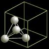

The content displayed on the left of the
figure is called Translational asymmetric
unit, while the one on the right is called
"nicely cut unit cell" or shortly Unit Cell.
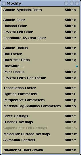
Modify menu has the following items:
Atomic symbols can be customized (edited).
Different fonts and colors can be assigned to different
labels.
Read more
...
Pops-up toplevel window, where colors for
individual elements can be set.
Read more ...
Pops-up toplevel window, where color for
unicolor bonds can be set.
Pops-up toplevel window, where color for crystal
cells can be set.
Pops-up toplevel window, where the color of the
coordinate system ban be set.
Read more ...
Pops-up toplevel window, where chemical
connectivity factor, spacefill factor and covalent
radii for individual elements can be set.
Read more ...
Ball factor can be modified here. Ball factor is
used for calculating the ball sizes (BallStick
display-mode). Ball size is defined as:
ball_seize =ball_factor * spacefill_factor *
atomic_radius.
Sets the ball/stick ratio, which determines the
thickness of bonds (sticks) with respect to hydrogen
ball size. Thickness of sticks is defined as:
stick_size = spacefill_factor * ball_factor *
                        ballStick_ratio * hydrogen_radius
-->WireFrame's
LineWidth Sets the line width for
WireFrame Lighting-Off display mode.
-->PointLines's
LineWidth Sets the line width for
PointLines Lighting-Off display mode.
-->Crystal Cell's
LineWidth Sets the line width for
crystal cells (for line display-mode of crystall
cells).
-->Lighting-Off
outline width Sets the outline width
for all but wireframe lighting-off display modes.
-->Lighting-On Wire
line width Sets the line width for the
various lighting-on wires (for example, width of
wires for wire display mode of isosurfaces)
Sets the points size for PointLines Lighting-Off
display mode.
Sets the rod factor for crystal cells (for rod
display-mode of crystal cells). Rod thickness is
defined as:
rod_thickness = rod_factor *
                        hydrogen_covalent_radius
.
Tessellation factor can be modified here.
Tessellation factor determined the number of tessella
that form the spheres, cylinders, etc. The larger the
tessellation factor, the larger the number of tessella.
Using larger tessellation factor makes the molecule to
appear nicer. Use relatively large tessellation factor
for printing (cca. 50).
Read more ...
Here the OpenGL lights can be customized. One can
enable up to 6 light sources, position them and set
their properties. To set the lighting parameters is not
very easy and intuitive. At least basic knowledge of
OpenGL lighting is required.
Here perspective parameters can be modified. There
are three factors:
fovy,
front, and
back. The smaller the
fovy the larger the
perception of the perspective. With the
front
and
back factors the front and back clipping
planes are set. The smaller the
back parameter
the more the structure (=displayed objects) is clipped
from the back side. The
front parameter is
counter-intuitive, meaning the smaller it is the more
the structure is clipped from the front side.
Here the OpenGL material properties of atoms and
bonds can be customized (Materials). Also the
depth-cuing (i.e. fog) and anti-aliasing parameters can
be edited.
Pops-up toplevel window, where the "length" factor
for the force display can be set.
Read more ...
Pops-up toplevel window, where the display of
H-bonds can be configured.
Read more ...
Pops-up toplevel window, where parameters for the
display of the Wigner-Seitz cell can be customized.
Read more ...
Pops-up toplevel window, where molecular-surface
parameters can be customized.
Read more ...
Pops-up toplevel window for controlling the
animations. menu is active only the loaded structure
file contains more than one structure.
Read more ...
Sets the number of displayed unit cells in each
A/B/C direction.
Read more ...
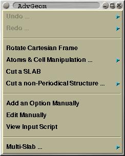
This menu is mented solely for CRYSTAL
GUI. Here one can manipulate an existing structure by
various procedures. Among supported options are: (i)
cutting a slab out of a crystal, (ii) generating a
supercell, (iii) adding, removing and substituting
atoms, ...
Here you can found
description of this menu and the usage
instructions.
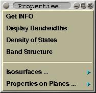
This menu is mented solely for CRYSTAL
GUI. Here one can perform some property analysis. Among
supported options are the plotting of (i) band widths,
(ii) density-of-states, (iii) band structure (one can
select th k-path inside Brillouin zone graphically),
(iv) electronic densities and electrostatic potentials
as 2D contours or 3D isosurfaces.
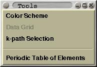
A few useful tools can be found here. This
includes:
Color Scheme, Data Grid, k-path
Selection and
Periodic Table of
Elements.
Pops-up toplevel window, where different color
schemes can be selected. Useful when examining the
structure (nearest-neighbor analysis, slab analysis).
If a DATAGRID section (2D or 3D) is present in
loaded XSF (XCrySDen Structure File) then this
menu-item is active. Via this option user will be able
to render 3D isosurfaces and/or 2D isolines and
colorplanes.
Read more ...
Renders Brillouin zone with special k-points.
K-path can be selected by mouse clicking these points.
So far, selected K-path can be saved only in
CRYSTAL-95/98/03 properties input-file format.
Read more ...
A toplevel window with Periodic Table of Elements
pops-up.


![[Figure]](img/xcrysden-picture-small-new.jpg)