
Tyler Susko
Mechanical EASY OFF button
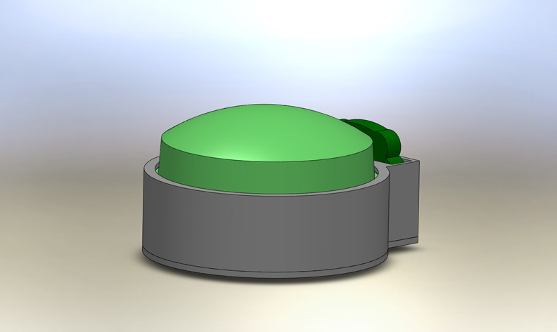
The Easy Button is a wired system that allows users to turn off the power from any outlet. This page details the mechanical design of the easy switch. Not shown in this solid model are the wires that would run from this switch to the power supply or outlet junction. The outlet junction, which allows users to plug anything into the easy button, is being designed by Heidi, another Ectera group member. In the on position, the plant is lowered as shown below. This occurs when the user physically pushes the plant down.
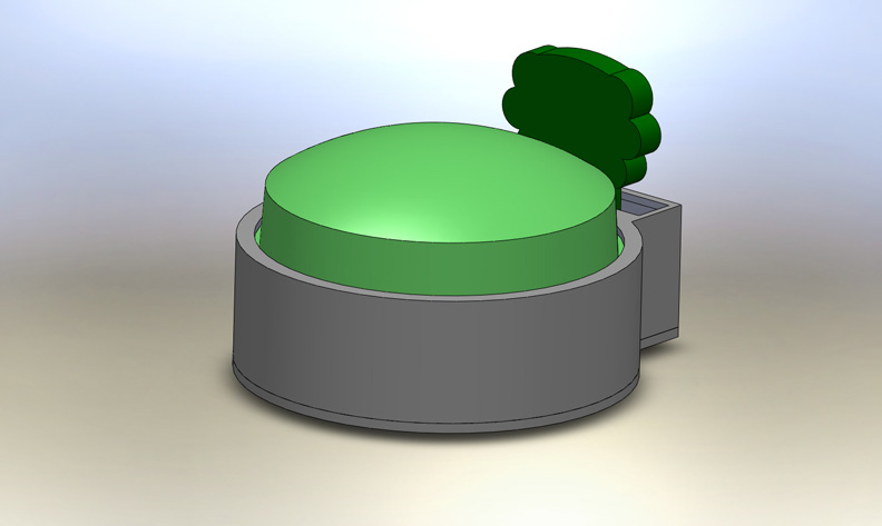
Below, the off position is shown. In the off position, the plant is full grown, indicating to the user that the power is off and energy is being saved. The off state occurs when the user presses the large EASY OFF button which will be clearly marked as can be seen in the storyboard.
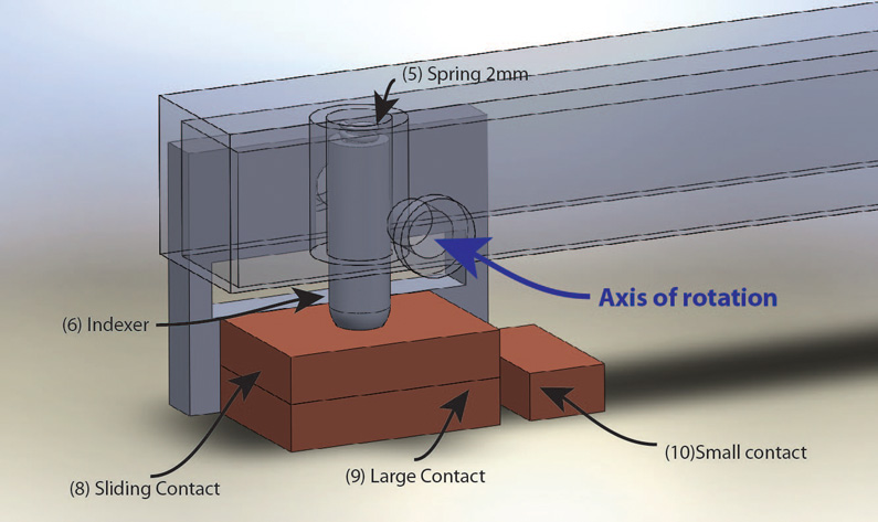
The following image shows the inner workings and construction of the EASY OFF button.
The following image shows the exploded view of the EASY Button, make reference to the below numbers for part details.
- (1) Upper Housing
- (2) EASY OFF Button
- (3) Lever
- (4) Plastic Plant
- (5) 1X Spring 2mm mean diameter, 15mm free length
- (6) Indexer
- (7) 2X Hinge Support
- (8) Sliding contact
- (9) Large Contact
- (10) Small Contact
- (11) 4X Spring 3.5mm mean diameter, 10mm free length
- (12) Bottom Plate
- (13) 4 x M3x10 screws
- *Not shown: Wires soldered to contacts

See the video below for a short animation to get an idea of how the components fit together.
The switching mechanism was based off of the design of a simple toggle switch seen below.
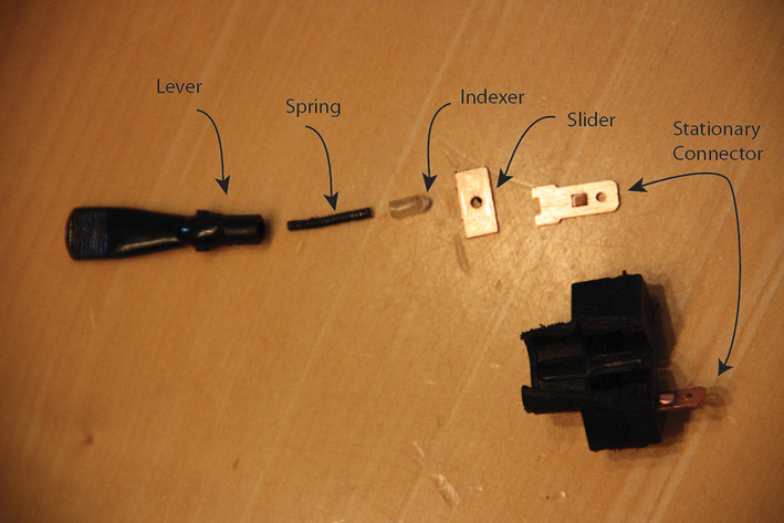
The slider is moved in and out of contact with the two stationary connectors. The spring and indexer serve as a positive position switch meaning that the system will automatically slide to each far end once it is moved past the center point. This phenomenon is created by the unstable point of the spring and lever. It is a similar feel to a standard light switch.
This was implemented into the EASY OFF button using a lever. The advantage of the lever is that when the button is depressed only a slight amount, the plant rises by about 7 times that amount determined by the ratio of lever lengths. Thus, if the button throw is 3mm, the plant will raise 21mm. There are other ways of doing this, but the lever seemed to be the simplest.
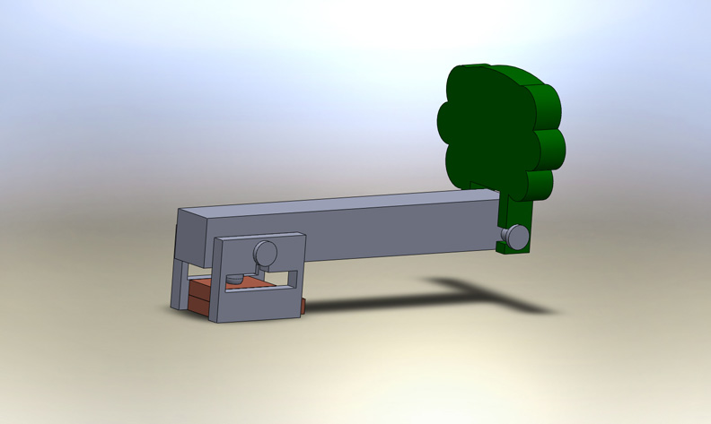
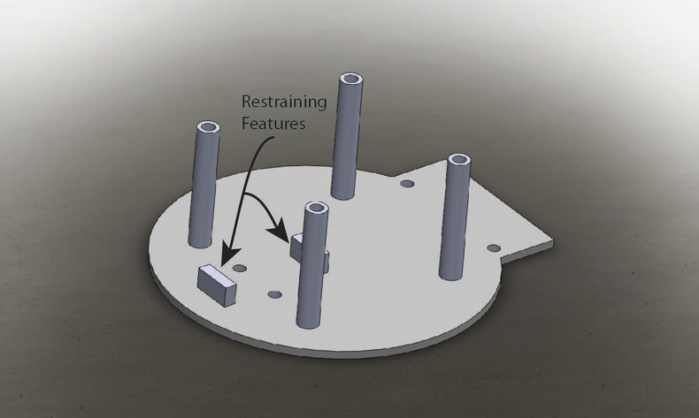
The following image shows the lever system a little more clearly.
The bottom plate has two raised blocks built in that will impede the motion of the lever to the correct sliding motion as shown below.
Future work and revision
At this point, you’ve probably realized that the small contact is on the wrong side of the large contact for the device to work as indicated. This change is minor in Solidworks but major in changing all of the images for this website. Secondly, there needs to be a screw and screw boss in the front of the unit. Right now, the design would not be robustly held together. Finally, in the next revision, a cord and outlet junction will be included.