
Overall Concept
NOTE: This is just a summary of the overall concept. For more details, please visit the team website.
The Design:
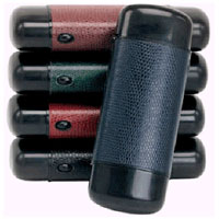
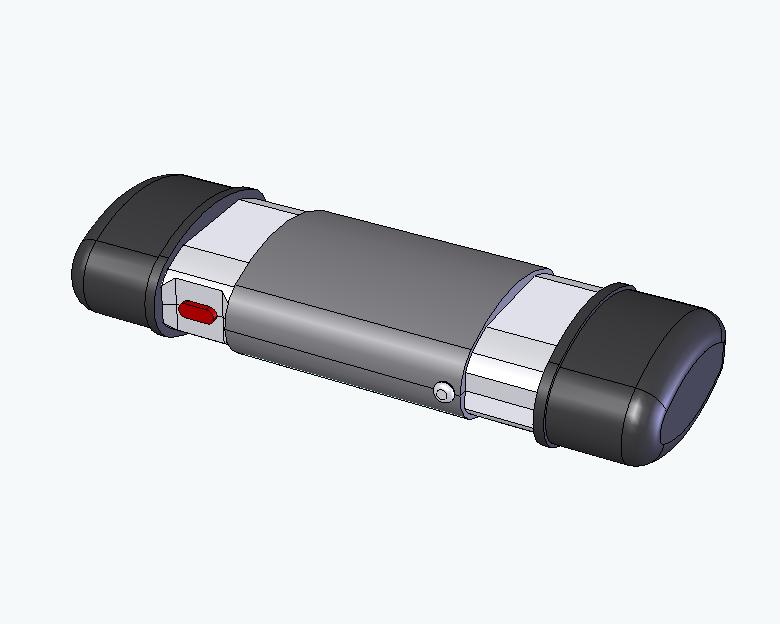
The scanner is concealed in a regular flip-top glasses case. When the user tries to open the glasses case like a regular flip-top case, the two ends pop out to reveal the scanner.


Operation:
Having opened the case the user is presented with a button and some illuminated symbols indicating the status of the device and how it needs to move over documents. Details on this can be found on Marko/Priam's Concept Refinement Site.
There is only ONE other button to push (besides the one that opened the case) and after seeing the symbols will let to user know that the device is a clue scanner and the button is the scan button.
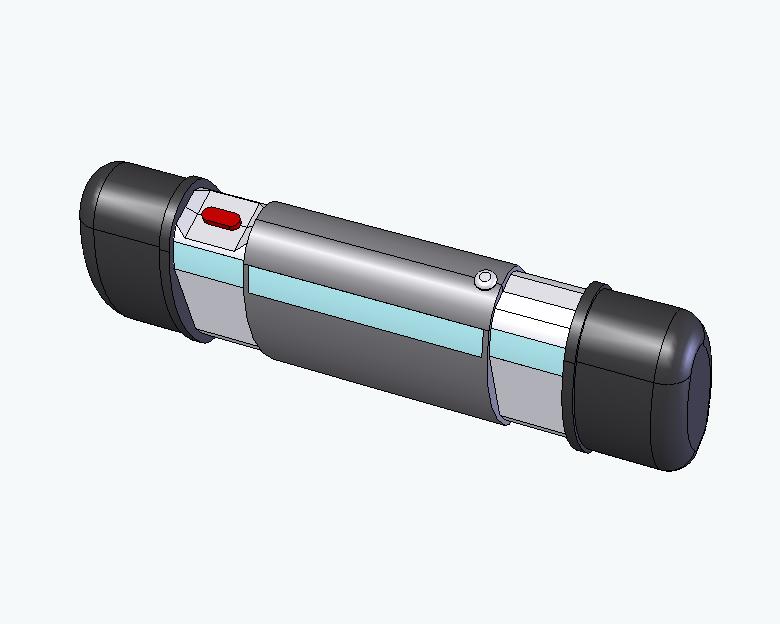
Holding down the button, the user "scans" the clue. A beam of light turns on and can be seen on the surface of the clue. All clues are 2D (on flat surfaces) but may be in a 3D location (e.g. map on the wall). When they are done scanning, they release the button and the lights on the device give feedback on whether the scan was successful or not. If successful, the user moves onto the next clue to be scanned.
In Context with the Spy Adventure:
The clue scanner is a concealed device that the guide carries in the “spy toolkit” the team bring with them for this operation. The guests will have been briefed in the briefing area on the tasks to be completed in the Director's Office.
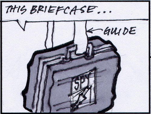
An eyeglass case was chosen because of the "coolness" factor of a concealed device and the connection the guests will make with the clue scanner to the concealed cameras (also concealed in glasses cases) they will see in the museum.
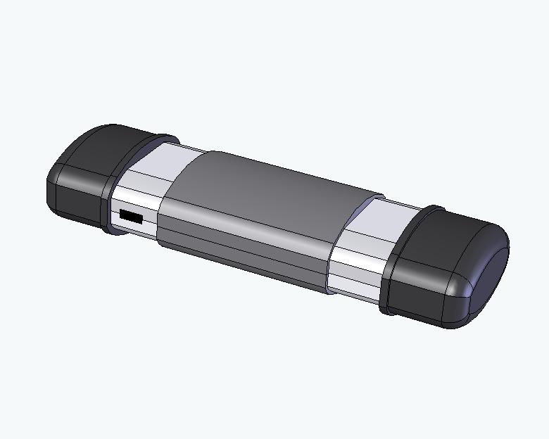
After escaping the Director's office and boarded the van, the guests hand over the scanner to the guide for downloading via a USB cable connected to a computer. Connecting the cable uploads the clue IDs to the exhibit control system, recharges the photoscanner and resets the photoscanner memory ready for the next group.
System Assembly:
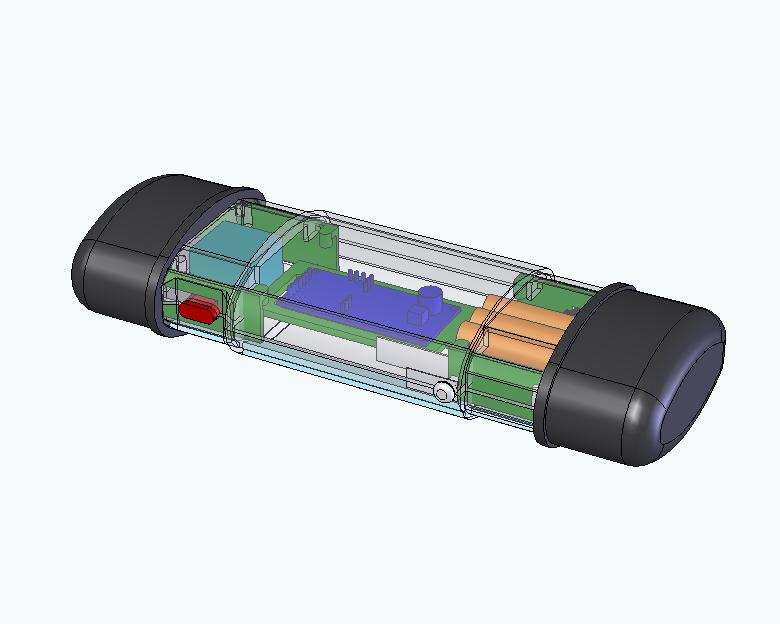
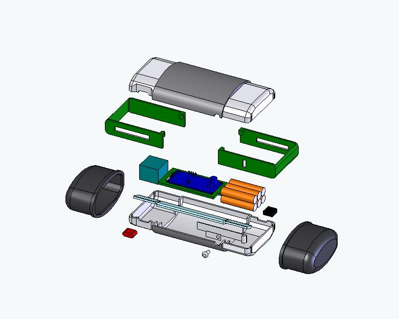
The major components of the photoscanner are the RFID reader module, opening/closing mechanism, battery pack, light beam and inverter, microcontroller and switches/active symbols.
Our design is assembled as shown in the following clip:
System Operation:
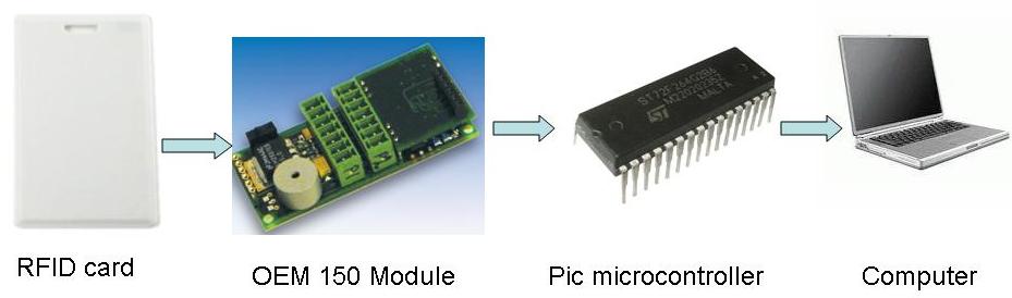
Our photoscanner is based around radio-frequency ID (RFID) technology. An RFID tag reader in the photoscanner reads the RFID tags embedded in the clues and gives the ID numbers to the microcontroller. This microcontroller remembers all the tags its seen and then downloads them to the exhibit control system when the photoscanner is docked. The exhibit control system can then adapt the storyline to match the clues that the guests found in the exhibit.
Additional functionality includes a variety of falsified user-feedback designed to give the impression of actually photoscanning the clues and a “low battery” warning that is actually telling the guide when the guests have found the four clues that are “critical” for completion of the Spy Adventure.