

Detailed Solidwork pieces that go into the overall assembly shown on the team website.
Top half of main body:
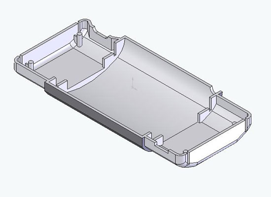
Roll mouse over to reveal features.
The design of this piece was to serve as a housing for all the hardware. The piece has three compartments, the main central one where the RFID reader will be located and the two ends where batteries, lights, and EL light inverter will be located. The two ends are smaller to accomodate for the flip-top caps that cover them when the scanner is closed.
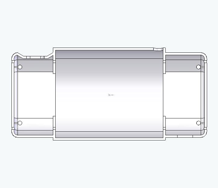
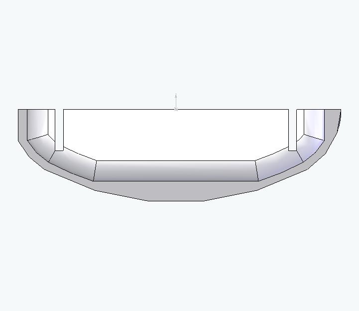
The ribs serve as structural support and also stops for the opening mechanism that extends the case to its full scanner length. There are also 4 posts to mount one end of the springs used in the opening mechanism. Slots have been cut out on the ribs and the ends of the end compartments. These are for the sliders that move to extend the device when the case is opened. Details on the mechanism can be found in Kartik's/Munhee's websites.
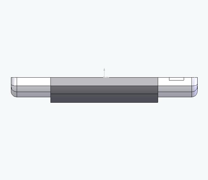
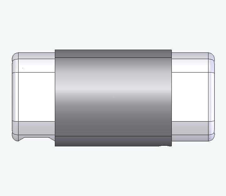
There is a dent on the side of one end where it is recessed for the scan button. Diagonal from it (if looking at the piece from the top) is the opening for the USB port. In one of the corners of the main compartment is a hole for the button to open the flip-top glasses case.
Bottom half of main body:
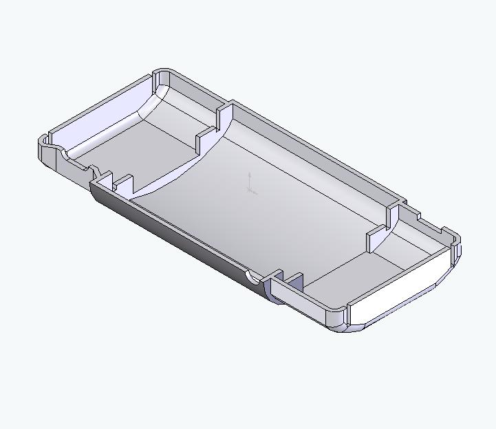
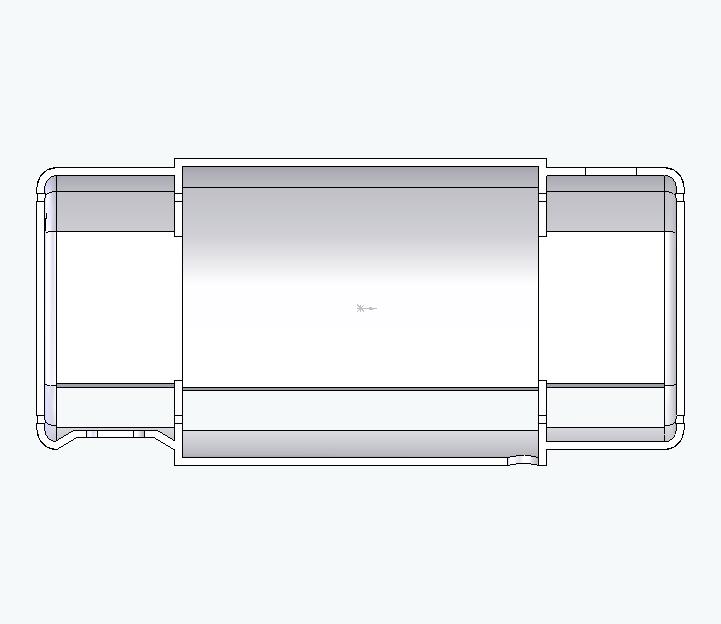
The bottom half of the main body is a mirror reflection of the top half, with the matching button holes and USB opening. What is different is the lack of posts for the springs in the opening mechanism and the slot cut out for the EL lights to shine through.
End caps of flip-top case:
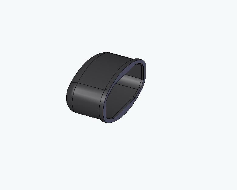
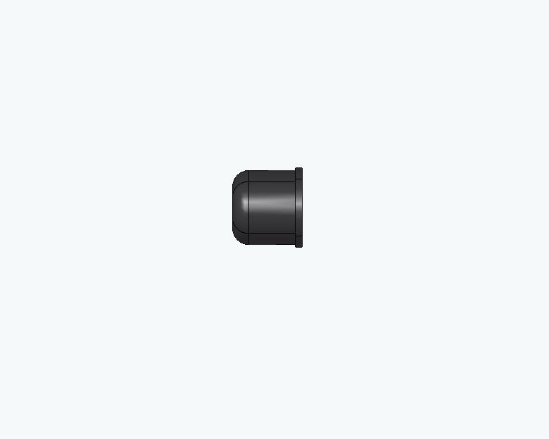
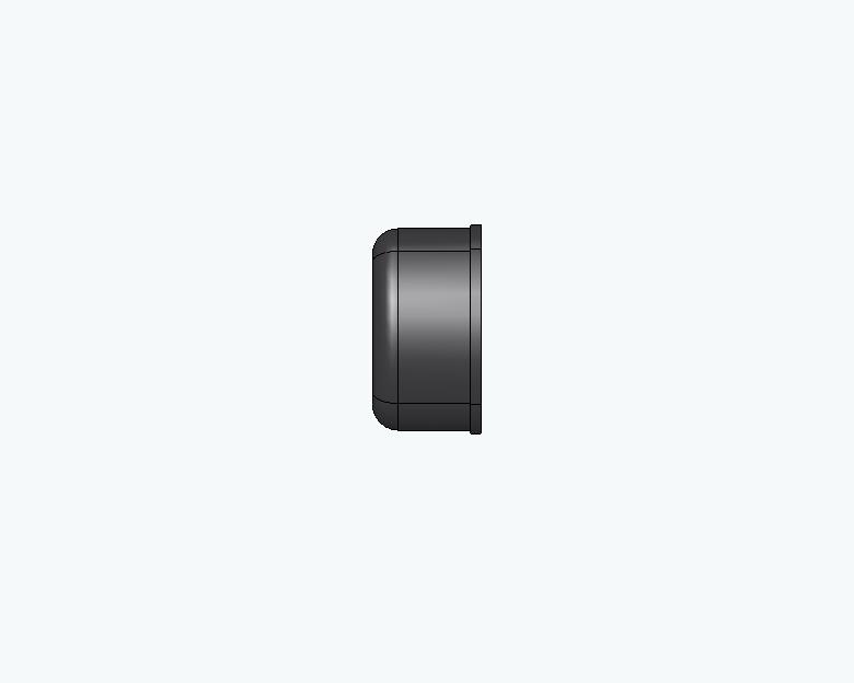
The caps look just like the caps on flip-top glasses cases. There is a raised lip on the caps so the device when used is rubbing againt those instead of the whole bottom surface of the case, maintaining that big cosmetic surface of the device.
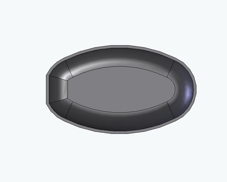
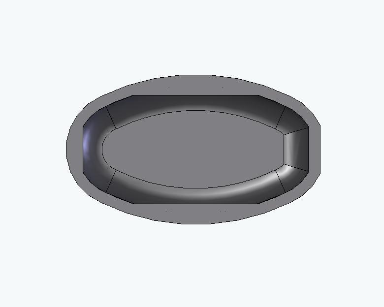
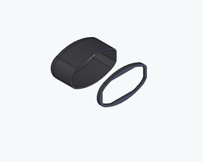
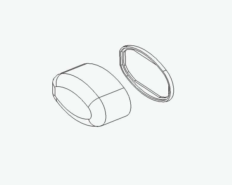
The cap is actually two parts, for assembly: (1) main body, (2) lip. The lip opening profile is the shape of the main body halves when put together.
Manufacturing Ideas:
The material for all these pieces are plastic. These pieces act as a casing for the RFID reader and thus cannot be metal or the reader won't be able to read the tags.
The pieces can be injection molded with a core and cavity but the number of pieces that need to be made are not justified. There are two options: (1) the design of the pieces can be simplified for other plastic forming techniques such as vacuum forming, or (2) the pieces would be manufactured through rapid prototyping with each piece finished by painting and preserving it with proper chemicals.
Any other ideas (simplification of design, processes, etc.) to manufacture these pieces cheaply for the small quantity needed (~15/year) would be greatly appreciated.