This section is divided into three parts. Navigate to the other parts using the menu on your left.
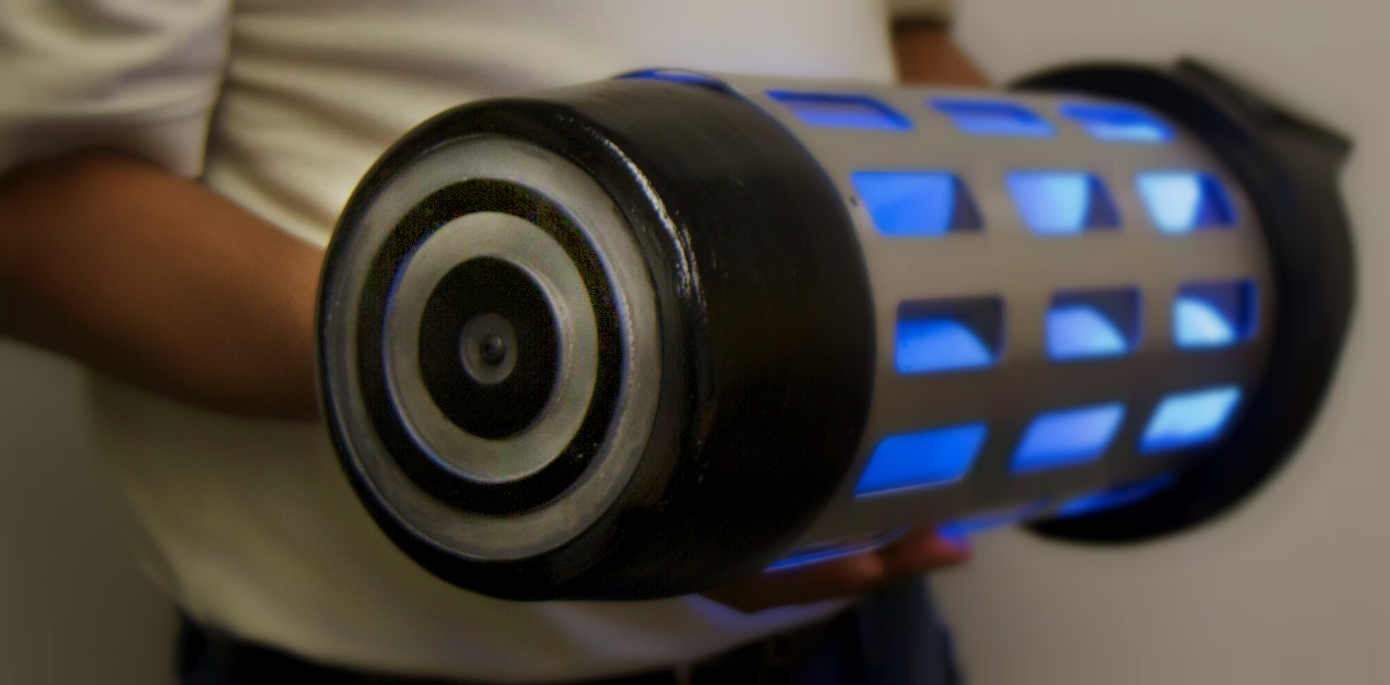
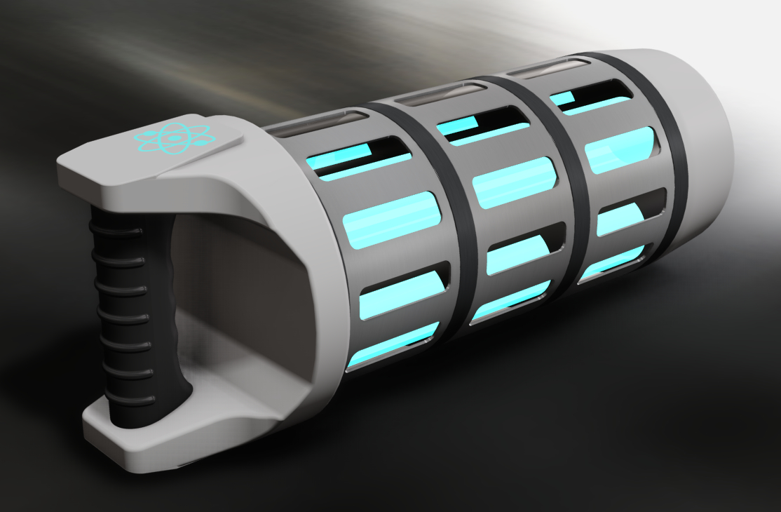
The fuel rod is a 2 kg handheld prop. It has a fluorescent liquid in four separate chambers lit with a hidden backlight. The lights are controlled and powered by an onboard recharghable battery and microcontroller. The mechanical structure is designed for strength required to bear falls and drops. The electrical components are designed to give consistent performance for long life without in-person maintenance.
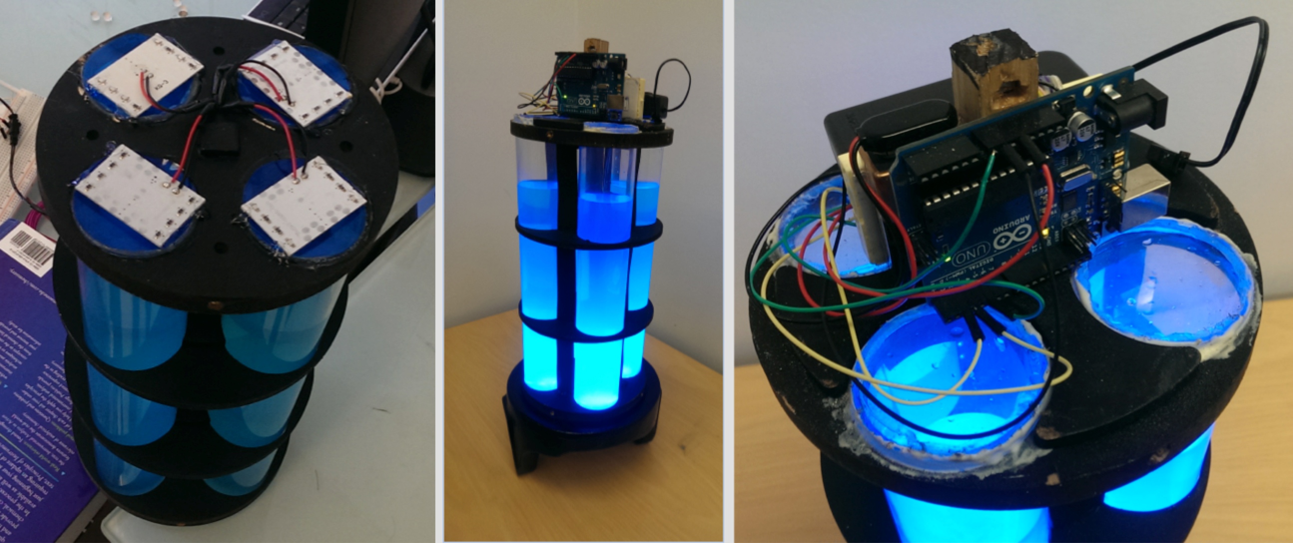
The rod's form factor has been considered in depth. Different color combinations and handle designs have also been considered. Below are two photographs of the final prototype.
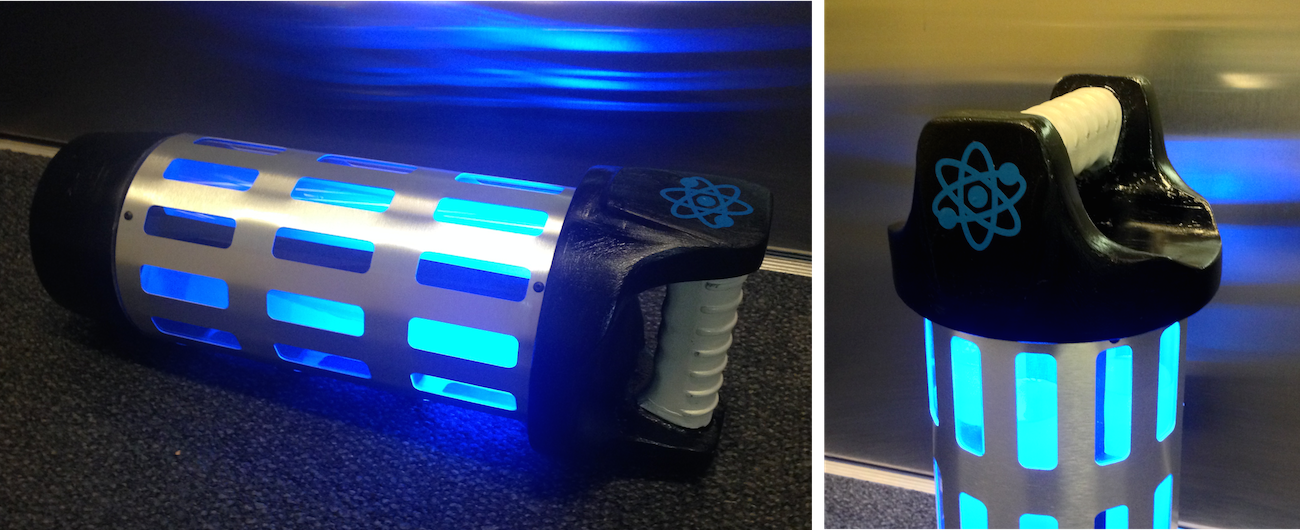
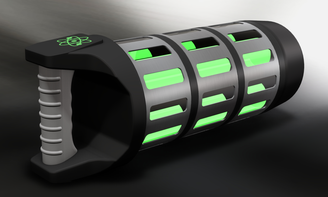
The design is adaptable to different SciFi styles. Different color combinations can effectively change the look to suit any storyline or theme. Below are two renderings of different color combinations. First for a classic SciFi look and second for a modern SciFi look. For the final prototype, we went with a hybrid of the two.
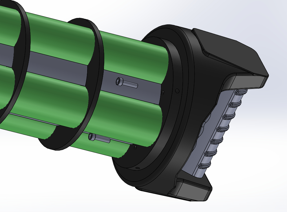
The explode views below illustrate the different parts that form the structure of the prototype.
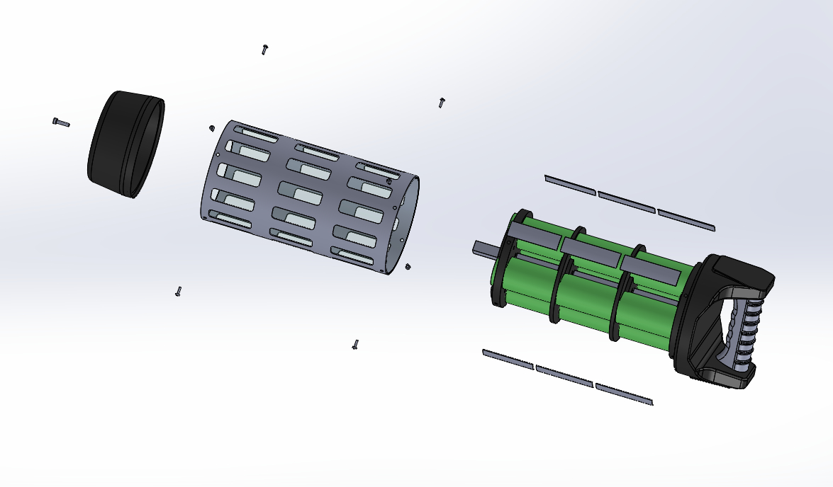
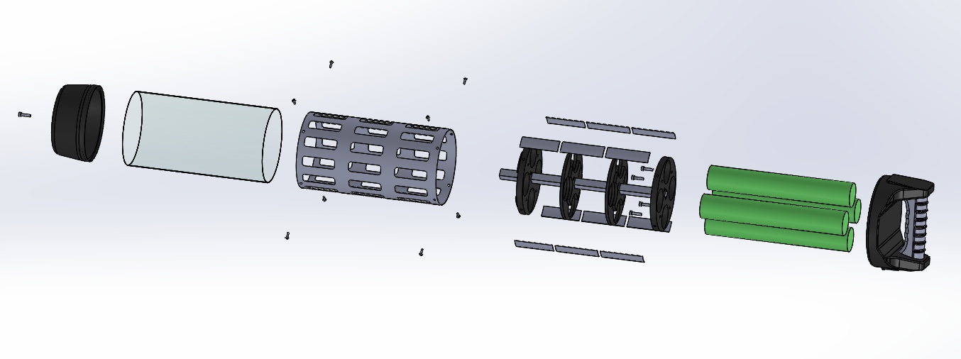
The core of this prototype is made of MDF and square wood dowel. (Find out more about alternative material and optimization proposals in the implementation section). The rod is mounted in a way that results in a rigid structure with light materials. A square wood dowel, four acrylic pipes and an aluminum case are all attached to same center pieces.
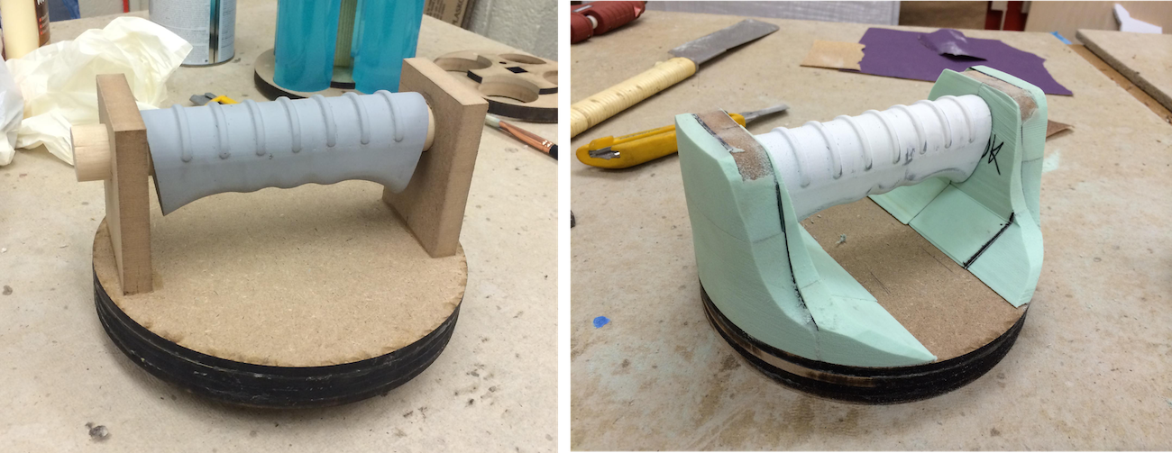
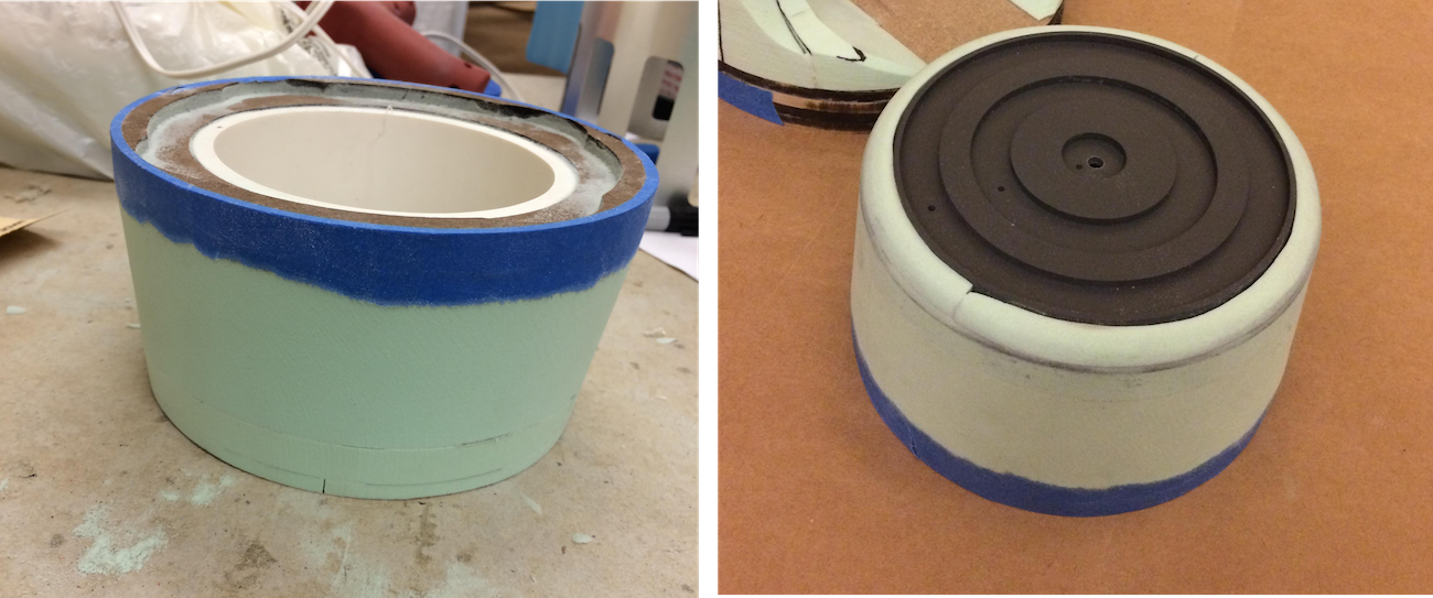
The complicated geometries of the handle and the front cap, for the purpose of a single prototype, are made through skill and precision. The following photographs below show how MDF, round stock, 3D printing, high-density foam, and body filler were used to create the shapes. The handle has an insert for housing the LED panels.
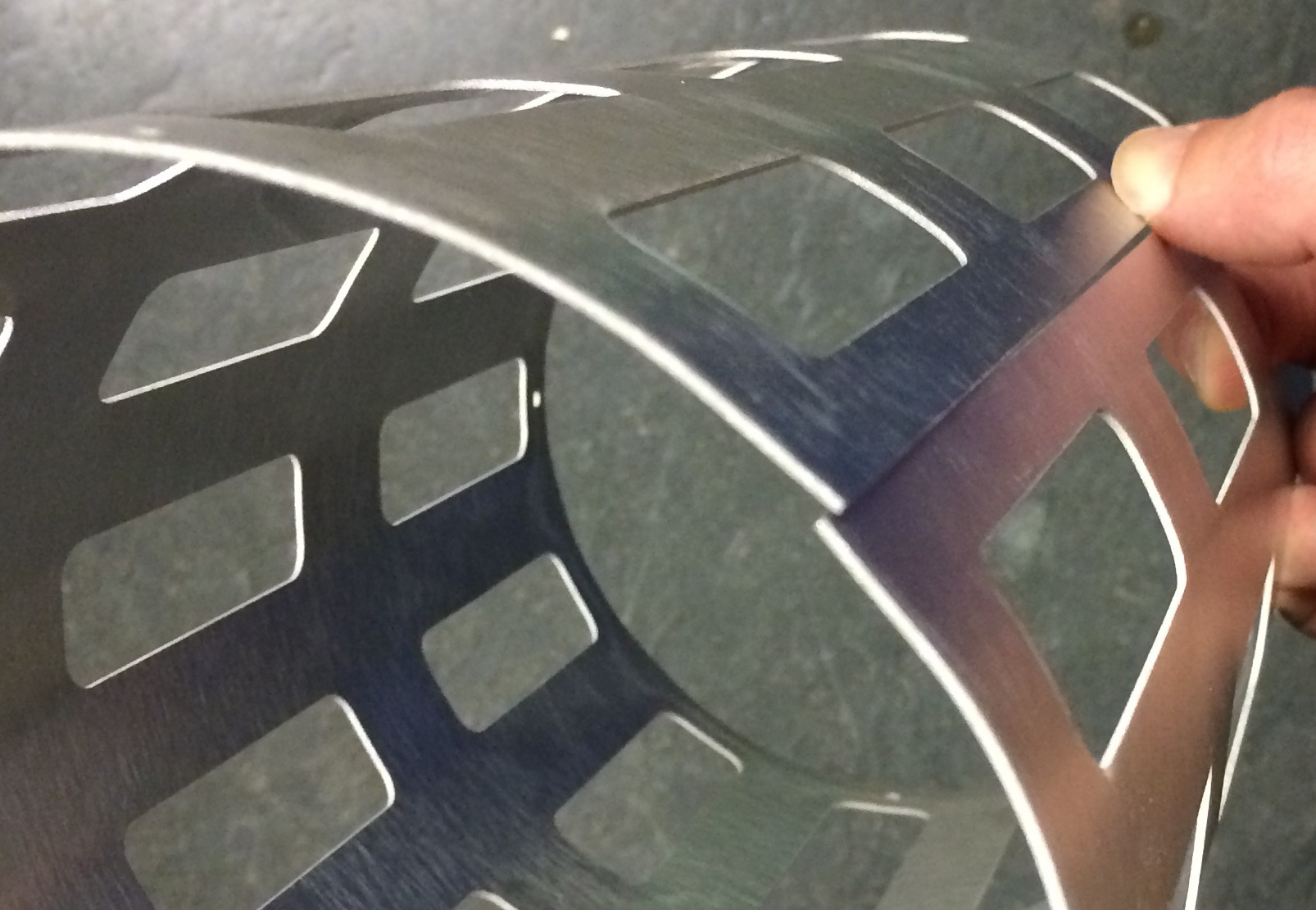
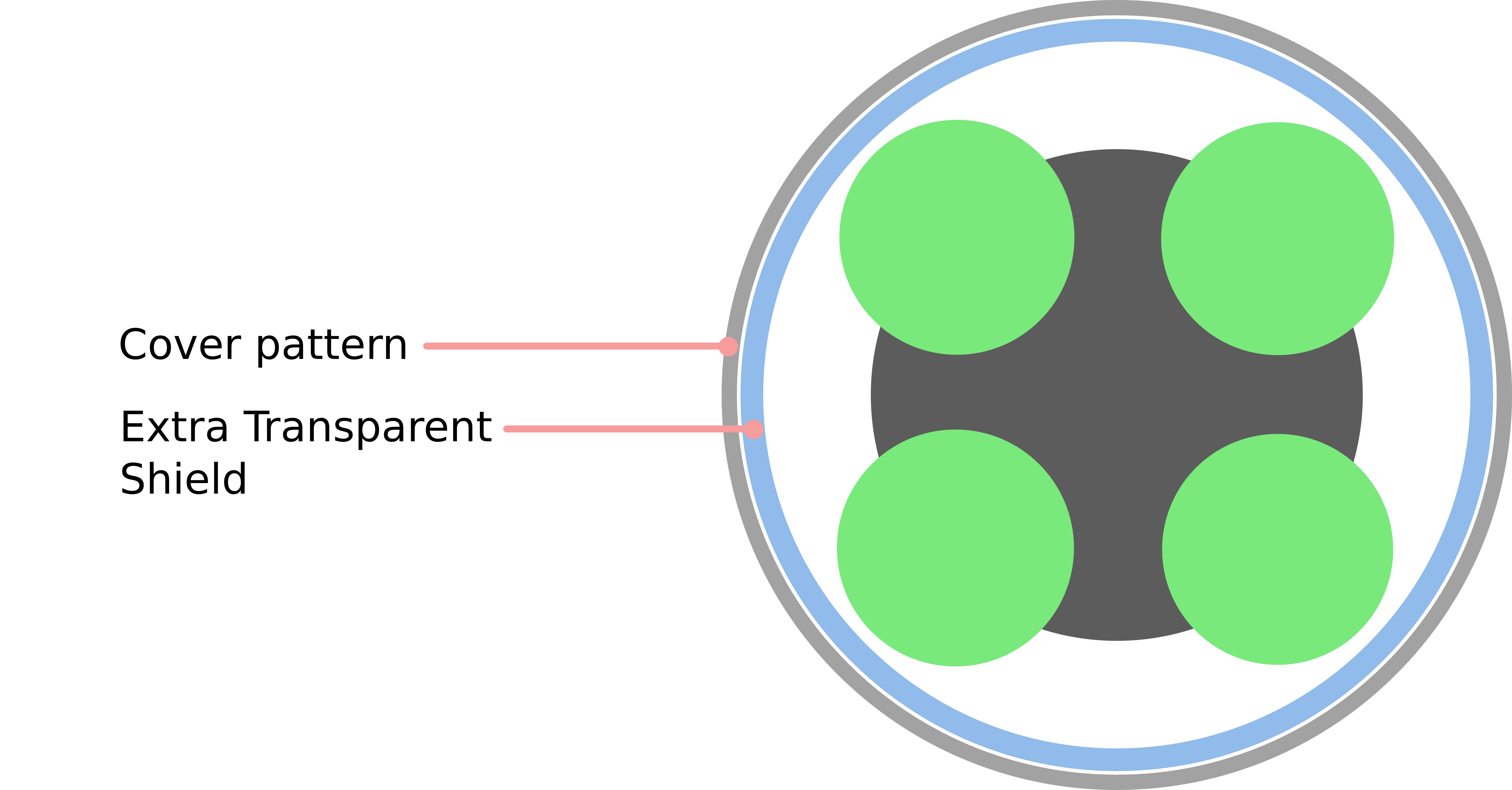
The case is made of a 0.04" bushed aluminum sheet. Before rolling the sheet, a pattern and mounting holes are cut using a waterjet. The rolled sheet is then TIG welded to create a solid and sturdy outer structure. A transparent plastic protective cover is placed flush with the cut pattern to ensure the visitors don't touch and stain the fuel chambers. It also acts as a safety feature to prevent fingers from getting stuck. Even with a transparent shield behind it, the outer pattern provides immense value to the experience. It adds to the realistic look, as a protection from nuclear fuel.
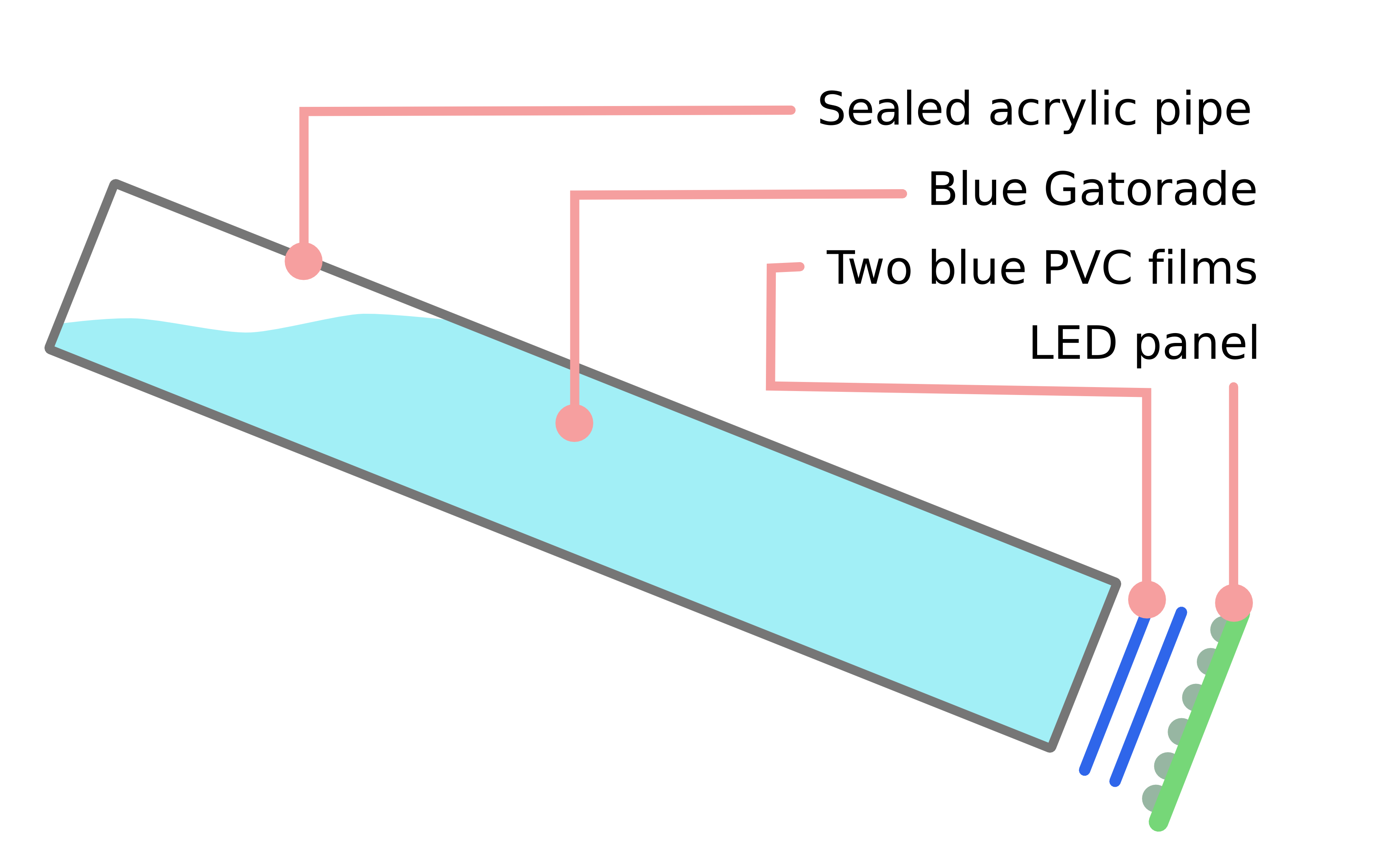
To create the glowing effect, four thin-walled polycarbonate pipes are filled with liquid, in this case blue Gatorade. Other brands and colors may be selected for different effects. The use of a off-the-shelf liquid has several advantages. It has a long shelf time, does not settle or leave residues, and is affordablea and readily replaceable. The pipes are sealed at both edges with flexible high-strength epoxy glue and a circular acrylic plate. This creates a good seal. Drop tests (see video in motivation) has not indicated any leakage. To create a uniform color effect, two blue PVC films are sandwiched between the pipes and the LED panel.
All components are bonded to the quarter inch thick center MDF plates. The handle is attached with bolts through the center plate that connect to inserts in the handle. The aluminum case in screwed to inserts in the two outer MDF plates.
The front cap is attached to an insert in the square wood dowel. The cap has a fitting along its edge, which keeps it from rotating. The acrylic pipes are glued to the MDF plats with an elastic high-strength epoxy glue. To cover the cables drawn trough the core, cutouts from a black plastic sheet are bent and epoxy glued to the core section. This is the reason why each large MDF section has smaller core sections attached to them; a nice and clean glue surface is needed.
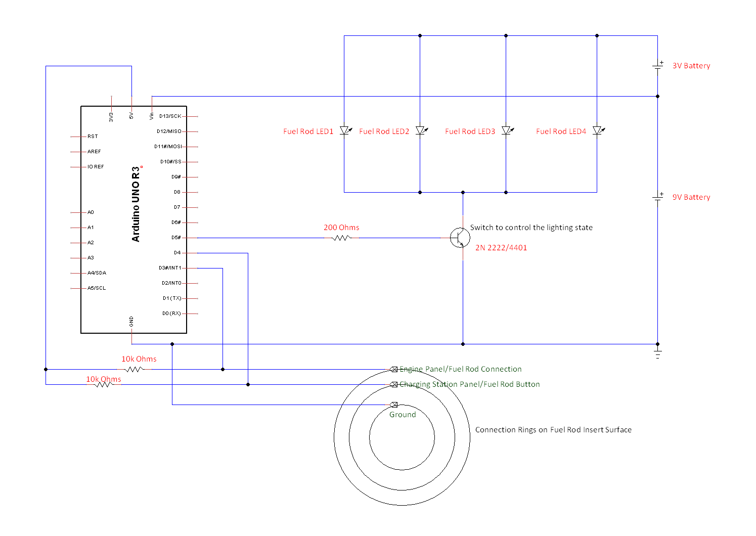
The four independent chambers are lit by four LED panels.Each panel has 24 high power white LEDs and are connected in parallel with a 12V potential difference to operate. The LED panels are positioned at the posterior of the fuel rod, near the handle. An ATMega 32 Bit Microcontroller is used to control the brightness of the LEDs. The microcontroller and the batteries are placed is in the head of the fuel rod.
In the present prototype, an Arduino Uno Development Board has been used and the switching cicuit has been built on a breadboard. Two separate batteries are used to provide separate operating voltages to the development board and the LED panels. These are temporary arrangements and can be replaced with a single battery and printed circuit board that is resistant to damage by shocks.
Three concentric Stainless Steel rings embedded on the Head serve two purposes. First, they act as sensors for the microcontroller to detect whether the fuel rod is inside a receptacle or not, and to detect whether it is in the charging station and the engine panel. Second, it serves as terminals for the batteries to charge every time the it is in a receptacle. The three rings are connected to the microcontroller with pull up switches, and to the power management circuit (not prototyped).