This section is divided into three parts. Navigate to the other parts using the menu on your left.
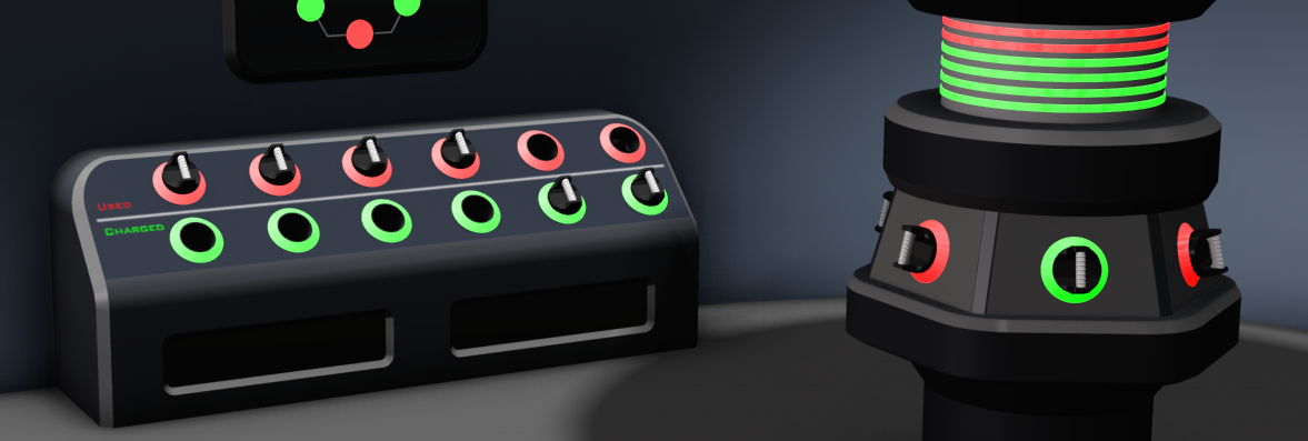
The panels are like tiles that combine to form the engine and the charging station. One trapezoidal engine panel and one rectangular charging station panel are prototyped. They have bright fluorescent lights pouring out from hidden crevices. The lights are controlled and powered by a central electrical control. The structure is designed for visual appeal and physical strength. The electrical components are designed to give consistent performance for long life without in-person maintenance.
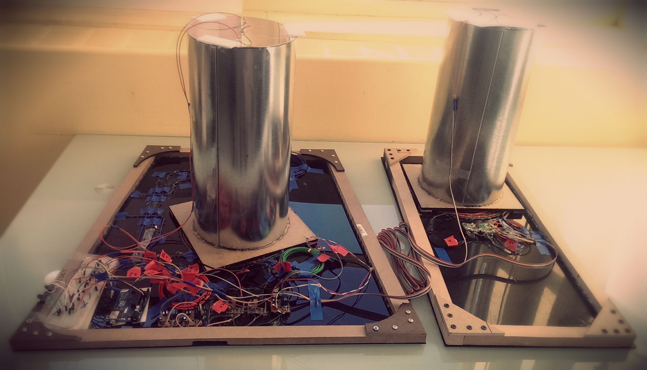
The engine and charging station are designed in a way that they do not take considerable floor space, and yet look overwhelming and bigger than life. Different color combinations and surfaces for the panels were considered. Following are photographs of the two panels.
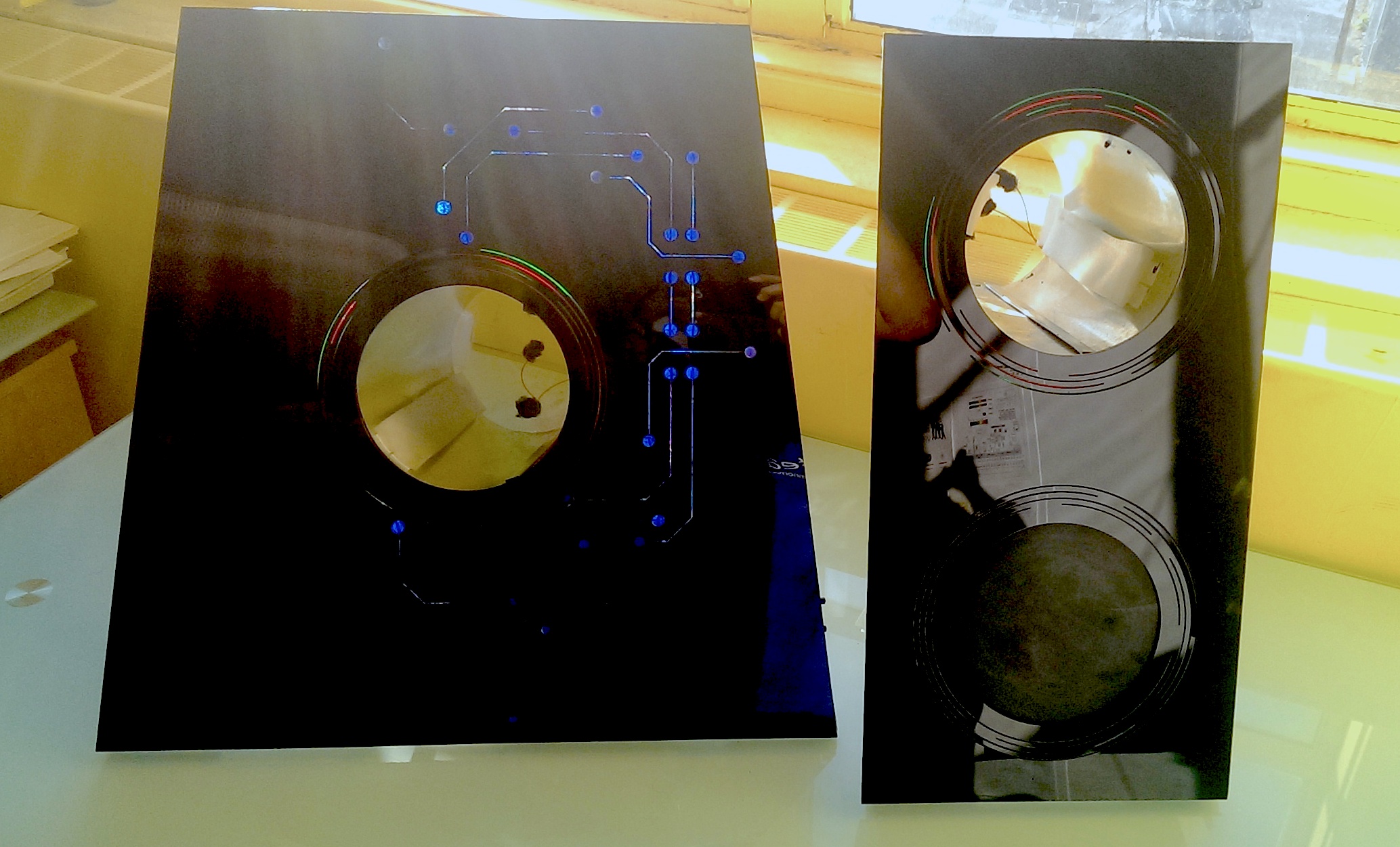
A glossy black surface is chosen to give a strong contrast to the thin lights and circuit patterns. A matte finished mettalic surface is an alternative that may give a more mechanised look.
The panels are made of rigid acrylic sheets. The holes for the receptacles and the circuit patterns are cut using a laser cutter. The acrylic sheet is reinforced with a custom made MDF frame, as in the photograph below.
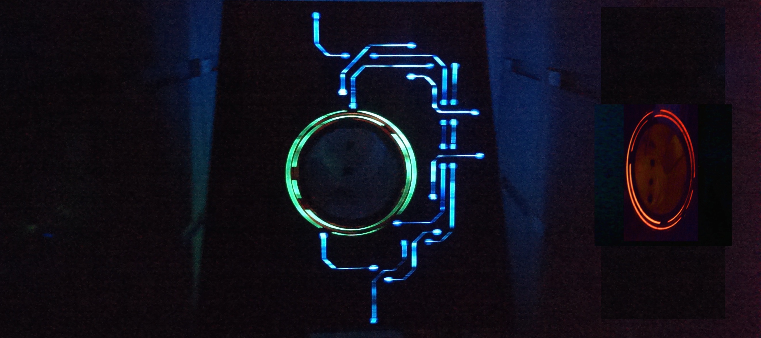
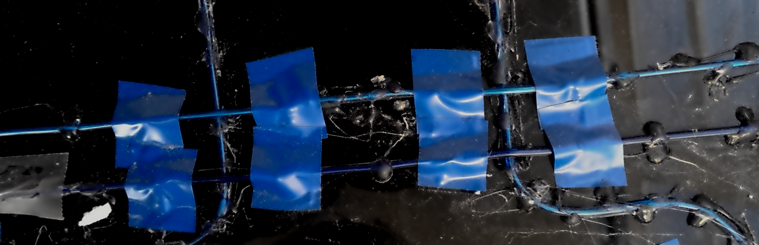
Strips of neon lights are glued on the crevices at the back of the panel.
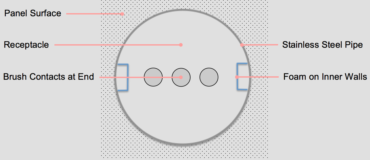
The receptacles are made using 7 inch stainless steel duct pipes. The inner walls are lined with foam strips. The end is capped with an acrylic plate with brushed contacts acting as sensors.
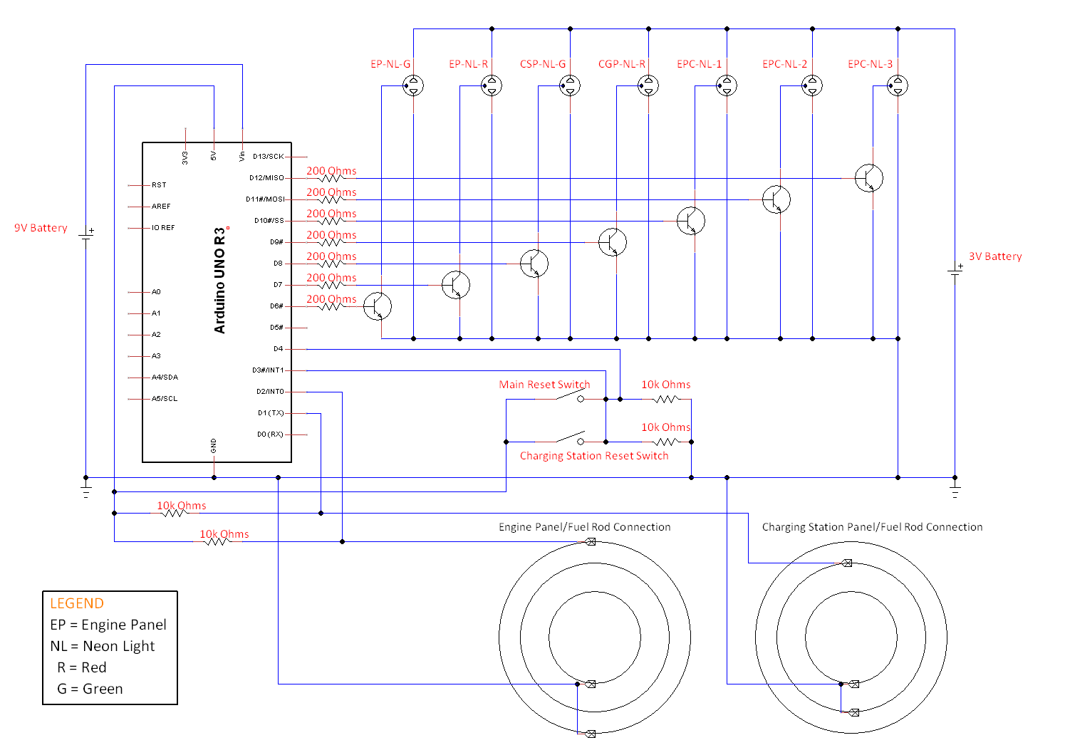
The ring of light circumscribing the receptacle and the circuit panel are lightd using controllable neon lights. Compared to stips of LED lights, neon lights provide a continuous glow. However, they are sub-optimal for the purpose because they generate a high pitch noise and don't give a strong visual effect. These problems can be mitigated with bent-tube neon lights that can be powered from the mains directly. An ATMega 32 Bit Microcontroller in the central electronic control is used to control the neon lights. The microcontroller and the power source are placed behind the panels, hidden from view.
In the present prototype, an Arduino Uno Development Board has been used and the switching cicuit has been built on a breadboard. A 9V battery was used to power the development board and a high current power supply was used to power the lights. These are temporary arrangements and can be replaced with a single SMPS and printed circuit boards.
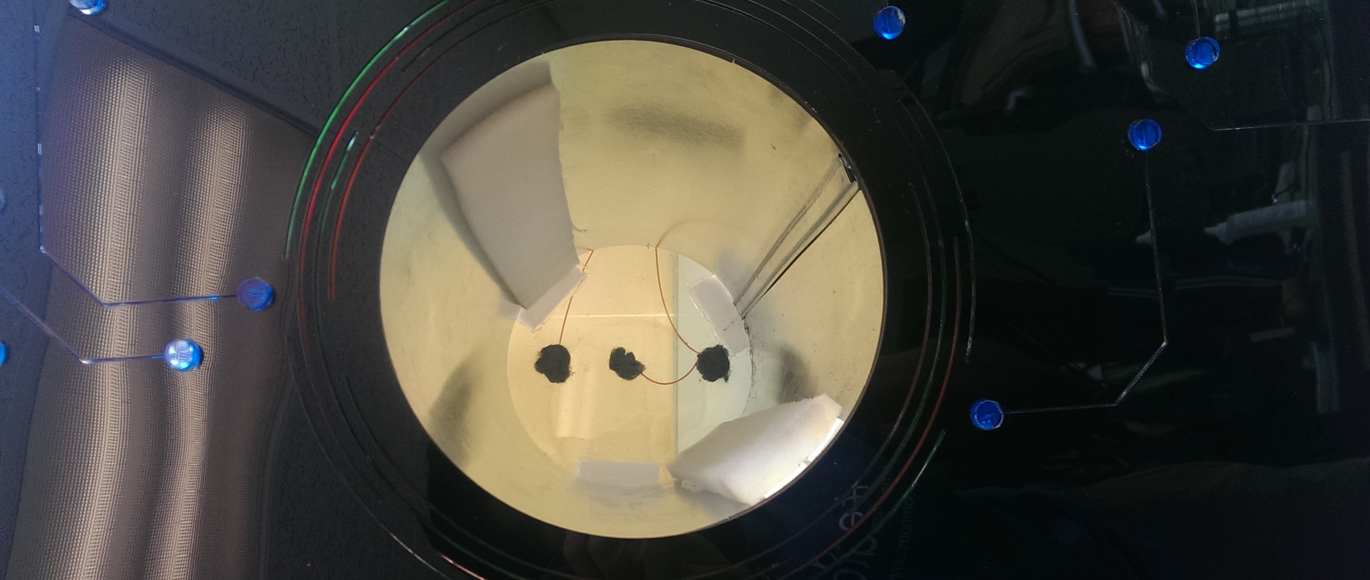
Interfacial electrical connections between the panels and the fuel rods trigger a sequence of lighting events. These guide participants to the next steps in the experience. Concentric rings on the head of fuel rods connect uniquely to the brushes in the receptacles. A three electrode dual pole switch using rings in the fuel rod and metalling wool in the panel slots.