 |
|
QUICK
LINKS |
|
-- Tsunami
Formation and Sensor Placement
|
|
-- Team 5 Home
-- Mission 2009
-- MIT |
|
|
Sensor
Deployment Methods
Overview
There are many different ways
to deploy buoys and their moorings. The methods used in deployment
can vary widely, but are based upon the buoy’s size, the conditions
of the water that is being monitored, the depth of the water the buoy
will be moored at, the delicacy of the instruments, and the resources
of the organization deploying the buoys. In general, small buoys less
than 300 kg such as weather buoys or drifter buoys can be deployed by
a small craft and one or two people. There is also an option to
attach buoys with particular instruments to an already-present moored
“mother” buoy. Finally, especially rough waters may warrant the
use of helicopter deployment. They tend to be used more often for
event-triggered observations, rather than long-term buoy placements.
DART-style buoys are very large, displacing over 4000 kg water
(http://www.ndbc.noaa.gov/Dart/dart.shtml),
and thus require the use of larger boats that have A-frame structures
and cranes. Helicopters are impractical due to the distance the buoys
are deployed from shore. This type of deployment requires up to ten
crew members actively working on the boat deck (Dever), and
deployment sites are many hours from shore. Weather conditions must
be carefully watched to ensure success. Buoys must be serviced every
1-2 years.
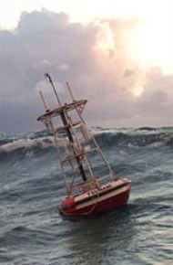
Deployment of a
tsunami DART buoy.
If possible, the buoy
or the satellite transmitter should be turned on and tested at the dock
before it is transported to the mooring site. Water current direction
should be determined near the mooring site, and the ship should move
down-current of the site. Drop locations are programmed into GPS. The
buoy is released at a distance of two-thirds of the mooring length. The
method for releasing the buoy will be described shortly. The boat will
then steam upstream past the deployment site until it runs out of rope;
this is done slowly and without any pressure on the rope so that the
buoy is not towed behind the boat. The boat will be at a distance of
one-third of the mooring length from the intended deployment site and
the boat will release the anchor. The anchor will descend through the
water with a pendulum-like motion until it reaches the bottom, which
will take approximately fifteen minutes. The tension increases to a
maximum just prior to contact with the sea floor (Gates 25-27, 32).
The sequence of components on the boat deck should be carefully mapped
out to prevent tangling and other snares. The mooring rope should not
pass over sharp edges, and everything should be arranged so that no
person must ever be positioned between the components and the
deployment point (usually the stern of the boat). The rope, chains,
anchor, and buoy should each be arranged and secured on the deck prior
to leaving the dock if possible. Assembly of any parts should take
place either on dock or on the boat deck if tools are available on the
boat deck (Gates 28-29).
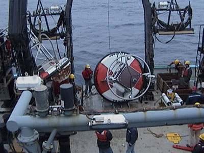
A crane, in
conjunction with an A-frame, which is a large, u-shaped structure that
extends up and over the stern of the boat, and winches, machines that
help regulate the raising and lowering of rope, is used to get the buoy
and anchor off the boat deck. The crane will pick up the buoy and move
along the A-frame until it is over the water, then slowly lower and
release the buoy. Once the buoy has been placed in the water, the chain
is slowly let out for the anchor as the boat moves upstream, but no
load is allowed on the chain. The heavy anchor is deployed in a similar
fashion to the buoy, using the A-frame and a crane (Dever).
To recover a buoy system, the buoy is caught using a hook and lifted
from the water onto the boat deck using the A-frame and a crane. Once
removed from the water, the load is taken off the anchor and a bull
line is attached. The anchor is then slowly winched out of the water
and brought upon deck, using the A-frame and a crane (Dever).
The bottom package,
consisting of the seismometer and a BPR and tsunameter, is deployed in
a similar way at a short distance from the buoy mooring. It will be
slowly lowered to the water’s surface, and then the anchor and the
bottom package will be allowed to free-fall to the ocean floor. They
are designed to work for 24 months. Units are recovered by a triggered
release from the anchor. The anchor system is not recovered for this
portion (http://www.ndbc.noaa.gov/Dart/dart.shtml).
The boat should then
check satellite connections to the buoy and ensure that the bottom
package has reached the ocean floor before moving back to dock.
�
 http://www.jamstec.go.jp/mirai/system_list/jpeg/A_frame.jpg
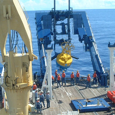
Deployment of a buoy using an A-frame at the stern
of a ship and a crane.
Bibliography
“Deep Ocean Assessment and
Reporting of Tsunamis.” National Data Buoy Center. Retrieved
10/11/2005 from http://www.ndbc.noaa.gov/Dart/dart.shtml.
Dever,
Ed and Harvey, Paul (2001). “CoOP/WEST Buoy Deployment and Recovery
Procedures.” Retrieved 10/11/2005 from http://shipsked.ucsd.edu/schedules/2003/nh_2003/dever/coopdep.pdf.
Gates, P. D., Preston, G. L., Chapman, L. B.
Preston. (1998). Roberts, M. (Ed.) (1999). “Fish Aggregating Device
(FAD) Manual: Volume III: Deploying and Maintaining FAD Systems.”
Noumea, New Caledonia: Government of Taiwan/ROC. Retrieved 10/11/2005
from http://www.spc.int/coastfish/Fishing/FAD3_E/fad3_e.htm.
Graphic
for banner on this page from http://www.noaa.gov/tsunamis.html
Photo 1 from http://www.ndbc.noaa.gov/Dart/deploy.jpg
Photo 2 from http://www.jamstec.go.jp/mirai/system_list/jpeg/A_frame.jpg
![]()