Non-Invasive Measurement of Blood Analytes using Raman spectroscopy
Instrumentation
Our laboratory has made significant advances in developing instrumentation and methodologies for non-invasive measurement of blood glucose using Raman spectroscopy. The objective has been to establish Raman spectroscopy as a viable approach for non-invasive measurement of glucose in vivo.
Laboratory-based Raman instrument
Our laboratory-based Raman instrument achieves extremely high throughput, and 30% of all photons back-scattered from a turbid medium are collected. The instrument employs a non-imaging, half-paraboloidal mirror as the primary collection optic, the specifications of which (f = 15.9 mm, collection half-angles 46º/30º, resulting in an effective numerical aperture of 0.5) were determined by an optical design software code (Zemax, Focus Software, Tucson, AZ). The design process involved careful study of spatial and angular distributions of the Raman signal from turbid media via experiments and Monte Carlo simulations. Raman spectra are excited at 830 nm and Raman emission is collected out to 960 nm.
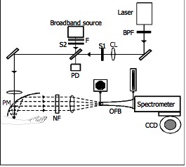
Recently, we have incorporated diffuse reflectance spectroscopy (DRS) in this instrument to correct for turbidity-induced sampling volume variations. The bimodal Raman and DRS instrument (Fig. 1) employs an 830 nm diode laser (Process Instruments) as the Raman excitation source and a tungsten-halogen lamp (Avantes AvaLight-HAL-S) as the broadband excitation source. A bandpass filter (BPF) (Semrock MaxLine 830) is placed at the laser output to remove unwanted spontaneous emission that broadens the laser linewidth. An RG850 absorption filter (F) is placed at the lamp output to reduce shorter wavelengths that cause scatter within the spectrometer. The filtered broadband source covers the wavelength range 850-960 nm. The two beams are independently shuttered (S1 and S2) and combined using an MgF2 plate at 45º, with the laser being transmitted and the white light source being reflected along the same beam path. A photodiode (PD) placed at this intersection monitors the power of both sources. The light sources are focused through a small hole (4 mm dia.) in an off-axis, gold-coated, half-paraboloidal mirror (PM) (Perkin- Elmer, Inc.) and delivered to the forearm or a fused silica cuvette (1 cm path length) filled with the sample of interest. The beam diameters at the sample are approximately 1 mm and the powers are 250 mW and 100 µW for the laser and broadband source, respectively.
Backscattered Raman and diffusely reflected light are collected with the half-paraboloidal mirror and sent through a holographic notch filter (NF) (Kaiser Optical Systems, Inc.) to reduce the magnitude of the excitation peak. Specular reflection from the cuvette surface passes through the hole in the paraboloidal mirror and is significantly diminished. Collected light is focused on the input end of an optical fiber bundle (OFB) (RoMack, Inc.) that transforms the circular shape of the collected light into a vertical line at the exit end (~ 400 mm x 26 mm). The exit end of the fiber bundle serves as the entrance slit of a modified f/1.4 spectrometer (Kaiser Optical Systems, Inc.). The light is dispersed by a holographic grating onto a 1300×1340 pixel liquid nitrogen-cooled CCD detector (Princeton Instruments).
|
Figure 1. Schematic of the laboratory based Raman instrument. BPF: bandpass filter; CL: cylindrical lens; S1-S2: shutters; F: Absorption filter; PD: photodiode; PM: paraboloidal mirror; NF: notch filter; OFB: optical fiber bundle; CCD: charge coupled device. |
Development of a portable instrument for clinical use
In order to carry out the clinical studies, we are building a compact, portable Raman spectroscopy instrument based on the current laboratory based Raman system. This instrument will be used for clinical validation studies on humans. Our laboratory has extensive experience in building such portable units, including one that is currently being used for the dog glucose clamping studies at the Indiana-Purdue Fort Wayne (IPFW) facility, maintained by Bayer.
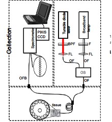
A diagram of the proposed portable instrument is shown in Fig. 2. It is modeled after the laboratory system but several design changes make it more compact and versatile. We will employ an optical fiber coupled temperature controlled tunable laser diode system, center frequency 830 nm, which will provide the capability of implementing the SERDS technique (described below) by providing laser excitation light that can be frequency shifted with a minimum resolution of 0.1 nm. An optical switch (PiezoJena) will be used to combine and control the laser and broadband sources. For light delivery and collection, we will convert from free-space optics to an optical fiber based system. In addition, a tunable wavelength spectrograph and a thermoelectrically-cooled PIXIS CCD (Princeton Instruments) will be used.
|
Figure 2. Schematic of envisioned fiber-optic based clinical prototype; BPF: bandpass filter; FL: focusing lens; S1-S2: shutters; F: Absorption filter; OS: optical switch; OF: optical fiber; OFB: optical fiber bundle |
Performance of the clinical instrument will be compared to that of the current laboratory system by measuring the minimum detection uncertainties for glucose and other analytes.
|
 |