
Vertical Elevator Motion Simulation
Introduction: The Gromits decided to make sketch models of various aspects of the lowering elevator gag. This sketch model was created to test the possibility of simulating an elevator’s lowering several stories while actually not displacing riders at all. The concept was modeled by pumping compressed air into three 1.5-inch-diameter bore pistons and controlling its flow as necessary. Below are images and accompanying descriptions that showcase the sketch model and its various components.
Please be sure to view the elevator story board before reviewing the sketch model below.
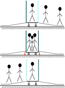
Overview: The above cartoon illustrates the intended use of the pneumatics under the elevator floor. The platform will be in its highest position, flush with the floor, when guests enter the elevator. Once the elevator-lowering simulation has begun, the floor will shake a bit, and the pistons will provide some “bumps”. The overall lowering distance of the elevator platform will never exceed the stroke length of the pistons, or roughly 5 inches. The guests will rise back up to the starting height of the lowering experience as the elevator “decelerates” when “coming to a stop” at the bottom of the simulated shaft.
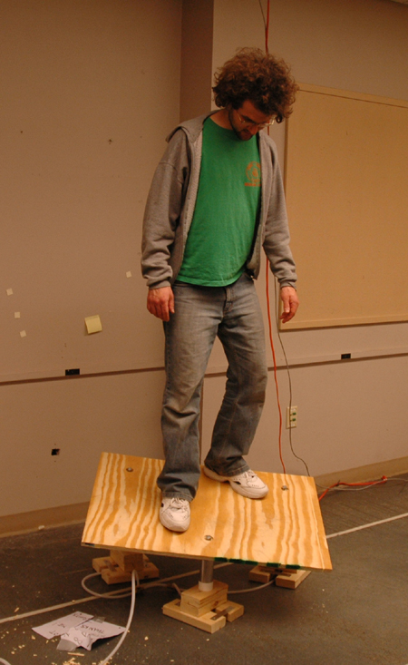
This image illustrates the overall working functionality of our elevator floor sketch model. As shown, the model was designed to raise and lower one rider in a controlled manner. Look how smiley Ethan is. He likes it!
 |
 |
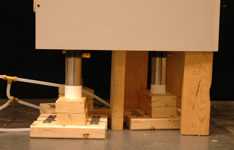 |
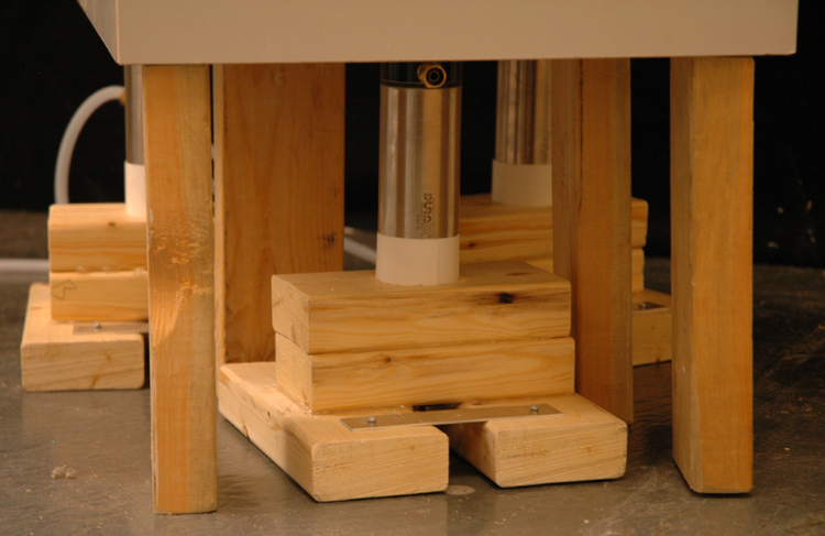
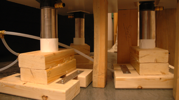
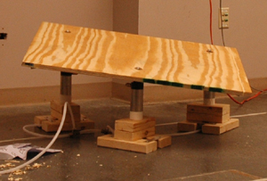
Piston base: The vertical motion of the elevator floor is achieved by using three pneumatic pistons. As shown above, the three pistons are laid out in a triangular configuration and braced with stacked 2 x 4 pieces of wood bored out to 2.25 inches to match the pistons’ outer diameters. To share the load of the structure above the pistons, vertical 2 x 4 pieces of wood are added to the bottom of the base. (Thanks to Dick Fenner for $300 worth of pistons!)
 |
 |
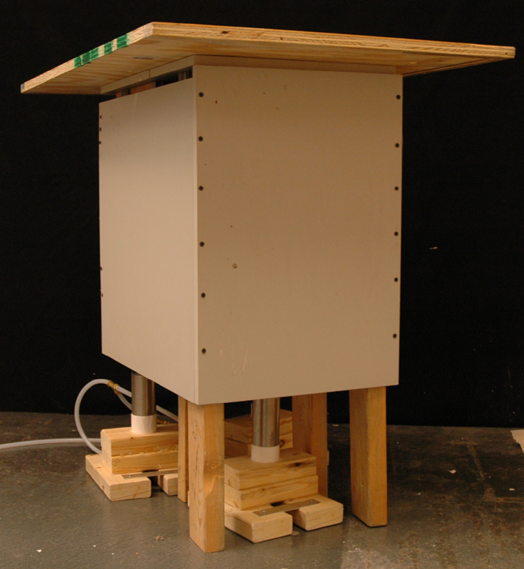 |
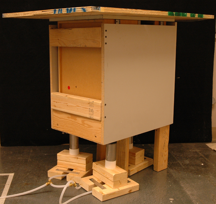
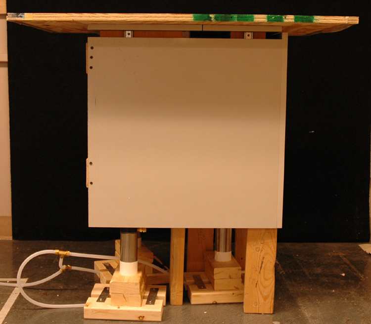
Structural base: The above three images show the structure of the elevator’s entire base. The main structure is composed of a filing cabinet on its end, multiple 2 x 4’s, and a piece of plywood. The filing cabinet is used because it is necessary to vertically constrain the motion of the top platform. The entire structure is reinforced with a multitude of 2 x 4’s and wood screws.
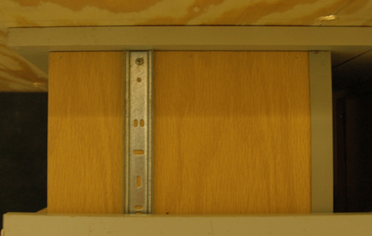
Sliders: The image above shows one of the sliders used as a vertical motion bearing surface. There are a total of four tracks in the configuration.
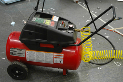
Compressed air network: This air compressor (courtesy of Prof. Dave Wallace), which is used to supply 100 psi to the pneumatic pistons, is red. The next few photos explain the pneumatic network used to supply the compressed air to the pistons.
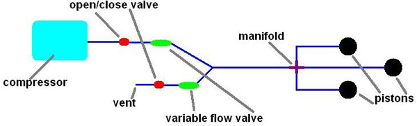
This schematic shows the configuration of the various components of the network. The air compressor connects to an open-close valve followed by a flow valve. The tube is split to include a venting branch to easily allow the elevator’s controlled descent. The main branch continues to a manifold, which unites the three pistons. All tube used is made of 3/8-inch polyurethane; all fittings are courtesy of Pappalardo Lab (thanks, Waterjet Bob!).
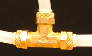
This tee is an example of the fittings used to create the manifold.
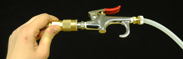
This is the trigger used to manually control the up-and-down motion of the elevator platform.
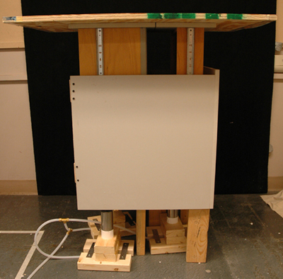
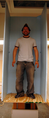
Functionality: This image shows the entire structure of the elevator floor sketch model. The floor is raised to its highest position, representative of the state of the system when guests enter the elevator. Note the two sliders visible from this side of the configuration.
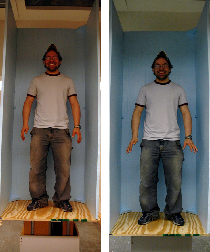
These images show Ethan and his twin brother riding two sketch models side-by-side. The images represent the ability of the model to easily raise and lower a single rider in a controlled manner. They also show the blue foam elevator walls that are attached to the setup to block surrounding visuals that might otherwise provide distractions to the tester. (Yes, to experience the full effect, he should really be looking the other way.)
To see a video of the elevator sketch model in motion, please click here.
Conclusions and Lessons Learned: We learned a lot from this sketch model! Not only did we get a better understanding of how the motion of the moving platform floor might simulate the actual descent of an elevator, but we learned about the use of pneumatics (and their instability), the physical constraints necessary to create vertical motion, and other important engineering phenomena.
The first iteration of the piston-platform setup was drastically different from the final sketch model. The original version consisted of the three bore pistons, which alone supported the moving platform. However, a network of pneumatics is unstable; because a perfect weight distribution is unachievable, the piston that supported the most load lowered, while the other two raised to compensate for the distribution. The increased height of the two pistons caused the lower one to lower even further, until enough time elapsed and all three pistons reached an equilibrium in the fully extended position.
 |
 |
As shown above, this first-generation platform was less than successful. Not yet realizing the problem with the platform was a matter of inadequate vertical constraints, the structure of the compressed air network was changed, the seals at every connection were improved, and an additional platform was added to constrain the pistons themselves to the same horizontal plane.
However, the necessity to constrain the motion of the platform to purely vertical displacement was soon realized. The use of a filing cabinet, with pre-made roller bearings to guide the vertical motion of the platform, instantly improved the performance of the sketch model. The vertical constraint forced the platform to rise at a uniform rate across its area; it also made the platform feel much more stable.
Multiple users tested the feel of the moving floor sketch model. Although each mentioned that the motion was jerky (an effect of manually controlling the piston motion that can easily be corrected using a proper control system), it was also mentioned that the sensation does replicate the lowering (and rising, if need be) of an elevator. When facing inward into the blue foam walls, every tester described the experience as "frightening" or "extremely disorienting".
The upward displacement of the platform, which occurs during the "deceleration" phase of the riders' descent, still needs to be faster and introduced by a smoother transition. Right now, the upward movement simply feels like upward displacement, and not like deceleration. We do not doubt that more finely controlled pneumatics and an increased number of pistons would achieve the proper effect.
If this effect were implemented in the elevator gag in Spy Adventure, the location of the pistons would change. The lack of vertical space, but abundance of space on the sides of the elevator suggest that the pistons would most effectively be located on the sides of the elevator car. With L-shaped braces supporting the elevator from the sides, this piston location should be easily implemented. Additionally, to support the weights of 15 people and 15 wheelchairs, more (or larger) pistons would be needed; nonetheless, this increased number should be easily accommodated, too.