 |
|
 |
Lecture on Basic Design Intent
Introduction
The design and modeling processes are inextricably interdependent! It is difficult and irresponsible to design processes, machines, or other products without modeling how they will look and perform. Parametric Solid Modeling (PSM) is a useful tool which will help you mathematically (geometrically) model your design(s.) It will also make your life easier and more productive as it will help:
|
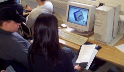 2.972 Students Making Solid Models |
The introduction of PSM does not mean the demise of sketching!!! Sketching is one of the most valuable skills a designer can have to quickly convey ideas and layout a design. As a matter of fact, it is often a GOOD idea to sketch out your designs before you proceed with PSM so that you can start to recognize the major shapes that make up your part. This is important as robust solid models are made of the fewest and least likely to change features one need.
PSM Process
Like the design process, PSM is best done when following a process. The general steps are listed below.
- Determine what you want to do/make
- Develop concepts for getting the job done (I.e. What are the best shapes to model this?)
- Determine your design intent design intent
- Draw/input any supporting geometry or sketches needed
- Draw a 2-D sketch
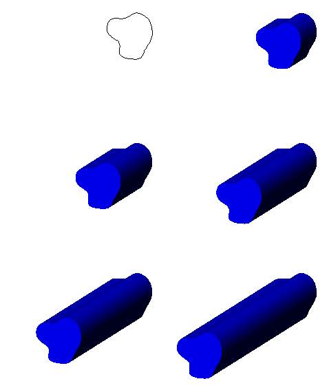
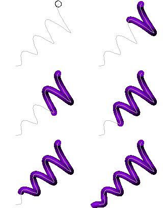
- Extrude, Revolve, Sweep, or Loft the 2-D sketch to make a 3-D object
- Combine these objects into assemblies
- Make drawing of individual parts and assemblies with dimensions & tolerances
- Make files for use with:
- Computer aided manufacturing (CAM) software
- FEA (finite element analysis) software
- Dynamic modeling software
- Photographic rendering software
Basic Functions in Parametric Solid Modeling
Before discussing PSM in more detail, the reader should be familiar with the basic operations which can be used to make a solid model of a part/product. Note that when applicable, the illustrations below start out with a 2D sketch, then are transformed into 3-D geometry. The basic process may differ somewhat, depending on the CAD program you use.
| Function | What its good for | Process
|
|
Solid Extrusions are often used to:
|
|
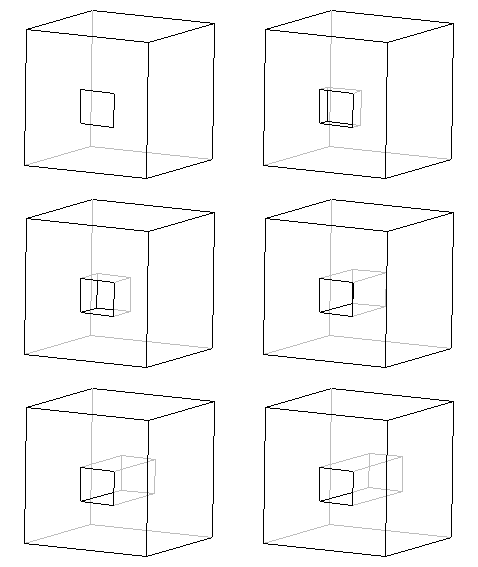 Cut/Slot Extrusion |
Subtracting portion of a model to
form a feature like:
|
|
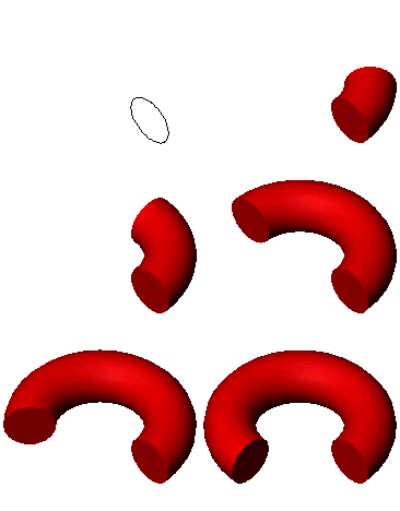 Revolved Extrusion |
Adding features to a model which
can best be described in R-q coordinates. These features
include:
|
|
 Revolved Cut |
Subtracting a portion of a model
which can best be described in R-q coordinates. These
features include:
|
|
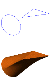 Loft |
Adding/subtracting features to a
model where two ends of the feature are described by different x-sections (sketches) and
the x-sections must transform into each other.
|
|
 Sweep |
Adding or subtracting parts to/from
a model which can best be described by "sweeping" a x-section along a
pre-described path:
|
|
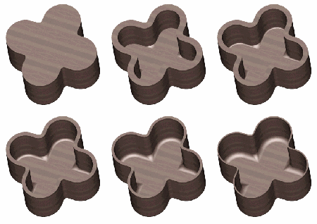 Shell |
Making thin parts such as:
|
|
Good Design Intent is the Key to Robust Solid Models
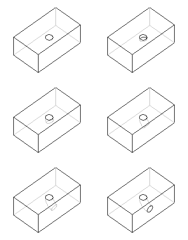
When we say "robust", we mean robust with respect to the design process. The goal of the PSM process is to make a model which can later be changed without messing up the original design intent. For example, suppose you have to make the piece shown below. The design intent is to have the hole centered in the middle of the cube. The correct and incorrect ways to solid model the part are shown in the table below.
| Correct Way | Incorrect Way | ||
| What was done | Result | What was done | Result |
| Draw a sketch |  |
Draw a sketch |  |
| Midplane extrusion |  |
1 Direction extrusion |  |
| Sketch hole centered at the midplane |  |
Sketch hole dimensioned from edge |  |
| Extrude hole |  |
Extrude hole |  |
| Change Base Length Design Intent Preserved |
 |
Change Base Length Design Intent NOT Preserved |
 |
We will cover more topics and go into detail on design intent in the lectures.
