
|
<< INTRODUCTION >> << OVERVIEW >> << AUDIO >> << GAMEPLAY >> << VIDEO >> << IMPROVEMENTS >> << ZBT RAMS >> << TIPS AND TRICKS >> << NES INPUT FSM >> << TOOLS >> |
Audio The iGamePlay audio component detects the beats that allow the enemy to move to the music. Using the lab kits on-board AC97 Codec chip and a simple energy comparison algorithm, the audio module was able to detect a range of beats from simple base drums more complicated techno and rap songs with strong down beats. The module would then relay the beat signal to the game logic to influence enemies speed. Getting Digital Audio Data AC97 Codec Before analyzing the music to detect beats, the analog source needed to be sampled with an A/D converter. Conveniently, the lab kit houses an AC97 codec chip that can do most of the sampling work. AC97 is a general PC audio codec specification published by Intel Corporation. You can view it here: http://www.intel.com/labs/media/audio/. The 6.111 lab kits contain the National Semiconductor LM4550 implementation of this specification. The LM4550 is in full compliance with respect to the features that it implements, but by no means does it implement every feature described in the Intel specification. For the purpose of iGamePlay, the LM4550 was more than adequate. The LM4550 audio codec is a powerful tool for digitizing analog inputs, processing analog inputs with its 3D sound circuitry, or playing back digitized samples from a ROM, however it cannot function without an AC97 digital controller. The controller is used for resetting the codec (necessary on power-on), reading digitized data from the codecs A/D, passing in digitized data to the codecs D/A, and modifying internal configuration registers (more on this later). Frame Protocol All communication between the AC97 codec and its controller occurs along two 1-bit serial data streams named sdata_out (from controller to codec) and sdata_in (codec to controller). These names are controller relative. Each stream is broken up into segments called frames. Each frame is made up of 256 sequential bits. The start of a frame is signaled by a control signal named SYNC that is generated by the controller. In a properly working controller, SYNC should transition from low to high once every 256 bits. In compliance with the specification, SYNC should have a duty cycle of 6.25%, in other words, it should remain high for 16 of the 256 bits. Any transition of SYNC from low to high before 256 bits have been recognized by the codec will be ignored. How often should a bit be sent across the 1-bit channel from the controller to the codec, and how often do bits come back from the codec? After coming out of reset, the codec will generate a bit clock at 12.288 MHz (half the 6.111 lab kit system clock speed). On the rising edge of the bit clock, the codec samples SYNC and the controller sends the first bit of the new frame. On the next falling edge, the codec samples the bit. Simultaneously, on the rising edge of the clock, the codec sends the controller 1 bit of information for the current frame. The controller is expected to sample the bit on the next falling edge of bit clock See Figures 2 and 3 below for timing diagrams. 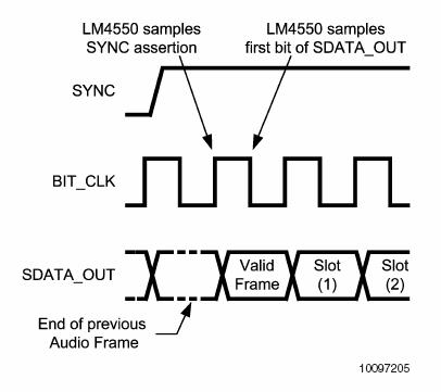 Figure 2. AC97 Output Frame (Controller to Codec) 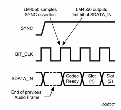 Figure 3. AC97 Input Frame (Codec to Controller) So the controller and codec communicate simultaneously across 2 1-bit channels by sending frames. What kind information is contained in each of these frames? The 256 frame bits are separated into 13 slots. The first slot is a 16-bit tag slot and the remaining 12 slots contain 20 bits each, as shown in Figure 4 below. The tag slot is essentially meta-data and describes whether or not there is valid data in any of the remaining 12 slots. The information in the remaining 12 slots differs between sdata_in and sdata_out and is described below.  Figure 4. AC97 Frame consisting of 13 slots
Frames from Controller to Codec Frames sent from the controller to the codec contain two valuable pieces of information. First, there is information used to write or read internal codec configuration registers. Second, there is digital audio data begin sent for processing by the codecs D/A. Eighteen bits of digital data can be passed to slots 3 and 4 (left and right channel respectively) or to slots 6 and 7 for D/A conversion. More important, however, is the information passed to configure the internal registers. Without properly configuring the codec, it will not be able to perform any of its powerful audio processing functions. Configuration Registers The AC97 specification contains a description of about thirty internal configuration registers that determine how the codec will operate. Several of these registers are configurable by the controller and, in many cases, must be written to for the codec to function. Among the most important are the registers which apply gain or attenuation on incoming and outgoing signals, and the selector mux which decides which input to listen to for incoming analog information. By default, all gain/attenuation registers are set to mute and the selector mux will listen on the microphone line input. Therefore, to see the desired functionality of the codec, all gain/attenuation registers in the critical path between inputs and outputs must be un-muted. The gain/attenuation registers can be configured between 0 dB and 22.5 dB with a 1.5 dB resolution. In addition to the gain/attenuation registers, the codec contains an 18-bit A/D converter with variable sampling rate ranging from 4 kHz to 48 kHz with 1 Hz resolution and again, there is an internal register that can be set to change this sampling rate. The iGamePlay system used the stereo line inputs with a sampling rate of 48 kHz along with the headphone outputs. Frames from Codec to Controller Frames sent from the codec to the controller contain two valuable pieces of information. First, the codec can send information to the controller in response to a register read. This information would include an echo of the register address requested for the read in slot 2, and the value stored in that address in slot 3. Second, the codec will pass back left and right channel digitized PCM data in slots 3 and 4 respectively. Analyzing Energy in the Music The beat detection algorithm used for iGamePlay is a modified version of an energy analysis method described here: http://www.gamedev.net/reference/programming/features/beatdetection/ . The basic intuition behind the algorithm is to find sections of the music where the instant energy in the signal is greater than some scaling of the average energy of the signal over the previous approximate second of music. The assumption made is that the instant energy in a signal will be much greater on the beat than between beats. This assumption is reasonable for songs with heavy down beats and little mid and high frequency noise. An outline of the original algorithm is as follows: The digitized sample values coming from the A/D are 18 bits 2s complement numbers which correspond to values ranging from (-2^15) through (2^15 1). For iGamePlay, these values were all shifted to positive numbers between 0 and (2^16-1) by flipping the most significant bit. By normalizing to all positive values we were able to remove the squaring operations in the above formulas. This is much more efficient because it does not require the use of an 18x18 bit multiplier and a 46x46 bit multiplier. Also, instead of diving by 32 to calculate This method, although sensitive to high energies resulting from higher frequencies, worked very well at tracking a various inputs. Basic tests involved songs with only bass drum beats at changing tempos, songs with bass drum and high-hats, and songs with a bass drum, high-hats and a bass guitar. The system tracked the beat perfectly for these inputs. More rigorous tests included techno and rap songs with strong downbeats. Although these songs had energy in other frequency bands, the algorithm performed very well and tracked the beat most of the time, losing its way from time to time, but usually getting back on track. Finally, we tested rock music with symbol crashes and high frequency guitar solos. The system did not track very well because this method for beat detection is colorblind. In other words, it only detects a threshold difference between the energies in the music, but does not know what frequency band the energy lies in. A more robust method would involve a frequency analysis of the incoming waveform using FFTs, filter banks or correlation functions.
|
 .
.