


|
<< INTRODUCTION >> << OVERVIEW >> << AUDIO >> << GAMEPLAY >> << VIDEO >> << IMPROVEMENTS >> << ZBT RAMS >> << TIPS AND TRICKS >> << NES INPUT FSM >> << TOOLS >> |
Input / Game Logic There are two obvious tasks in this section of the iGamePlay project. The input component must interface with users, ensuring that each player has a direct say in the flow and variation of any single game. The game logic component must preserve and update the continually varying game state, driving information about crucial game objects to the video output unit. User Input For the iGamePlay project, we decided to use two Nintendo Emulation System (NES) controllers as input devices. The gamer generation has extended familiarity with this device, and its use is straightforward. Beyond that, the system interface for NES controllers is rather simple. Unlike analog controllers and joysticks, the NES joy pad only has buttons. At any time, each button is either idle (off) or depressed (on). The only task that the user input module must perform is to sample all eight NES buttons at some frequency. 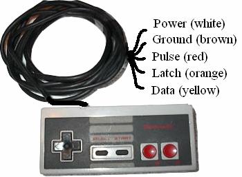 Figure 6. Physical Interface to NES Controller The physical interface to the NES controller is a simple one. Only five wires connect each NES pad to the iGamePlay kit. There are four controller inputs (power, ground, latch and pulse) and one controller output (data). Since there is only one data line, buttons states must be transferred serially. An input finite state machine within the project handles all controller communications, according to the input protocol shown in Figure 7. A latch signal from the input FSM initiates a transaction sixty times every second. Latch is held high for twelve microseconds, after which the first data value (A) is guaranteed to be valid. After reading the value, the input sends seven six-microsecond pulses out on the pulse wire. After each one, it reads a new button value from the data line, which the controller will drive there in the order B, Select, Start, Up, Down, Left, and Right. See Appendix D for Verilog code that implements this communication protocol.  Figure 7. Nintendo Emulation System Input Protocol A major concern with any asynchronous user input to a digital system is registering and steadying user data. In this case, the user presses keypad buttons that may bounce after the first touch until they finally settle. To prevent asynchronous data from ruining the careful timing of the digital system, the inputs are first registered on the system clock. In some scenarios, it is helpful to also build a button delay, to ensure that a user meant to perform the chosen action. For example, when the user chooses a menu option, the system waits for 100 ms of valid user data to ensure that any button press is intentional. However, such debouncing of user input is not always beneficial: when a user wants to shoot a missile, it is important that the action is completed immediately. Because demand for button debouncing varies even across different uses of the same keys, debouncing is performed locally as needed, and not dealt with in or around the input FSM. Game Logic Beat The game logic portion of the iGamePlay project is the section of code that is the least native to a hardware implementation. The game logic component is a large finite state machine built on several other game object FSMs. The interactions between the modules are often complex and tedious in hardware (i.e. collision detection), and as a result take up a lot of FPGA realty. Figure 8 shows an overview of the game logic component.  Figure 8. Game Logic Overview The minor FSMs for players, missiles and enemies are all primarily movement oriented. They control the positions of game objects in response to user input in the case of the players, a beat signal in the case of the enemies, and a targets position in the case of the missiles. However, such movements are predicated on the liveness of objects. Hardware restrictions do not allow the allocation of many missile or enemy structures, and as a result the viable number of missiles and enemies were experimentally capped at sixteen. At no one time will all enemies and missiles be active. Instead, the game logic cycles through idle (expired or collided) missiles, keeping track of the current missile and enemy indices, and reactivating them as new game objects with the spawn signal and a set of initial coordinates. When it is time for the game objects to disappear again (whether via expiration or collision), missiles and enemies are given an active reset signal. The operations that require knowledge about more than one game object all take place in the main game loop. The most visually prominent and also most difficult multi-object actions are collisions, which can lead to any of the following outcomes: player bounce, player death, enemy splitting, enemy death, and missile death. The reason why collisions are so tricky is that each collision requires several large comparators to check for proximity, and the total number of collision checks is in the hundreds. To solve this problem, the iGamePlay system uses a single collider module that checks proximity of its inputs. The system examines collision candidates in sequence, an inefficiency that is made possible by the high system clock speed. At a clock frequency of 27 MHz, and a movement rate of one tick per 100 milliseconds, the system has many thousands of clock cycles to check collisions between movements.  Figure 9. Game Loop Finite State Machine While the focus of the game logic is mainly on game play and game content, the main loop also performs several functions that gamers might take for granted in games. See Figure 9 for a diagram showing the transitions of the game loop FSM. The system deals with game play aspects in the PLAY loop: collisions (as described above), player death and victory, and missile firing. Beyond this, the system keeps track of levels, changing the level in the transition from PLAY back to SETUP. With each higher level, missiles and enemies speed up, presenting a larger challenge to the player, whose own speed remains unchanged. SETUP is a good place to provide level information to the video system, though project time constraints forced us to bypass this feature. The system also implements a Mario-style menu interface, allowing the user to switch a selector between editing game mode and starting a match. Finally, the WIN state provides an opportunity to present game results to the video system, which could output whether player one, player two, or the enemy won the match. Due to project time constraints, this implementation did not contain such a summary screen, instead skipping through to the RESET state. |