TMRS-3 - Hardware Photos
19GHz and 37GHz Radiometers
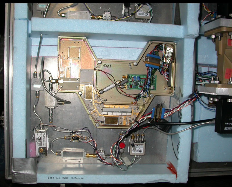
Some of the RF front-end electronics for the Truck Mounted Radiometer System III (TMRS-3) are salvaged for the most part from the TMRS-2 projects used by the MWGP group in the late 90's, specifically for the 19GHz and 37GHz radiometers. The layouts, cases, and backend support are all new. Below is a picture of the insides of the original TMRS-2 19GHz radiometer.
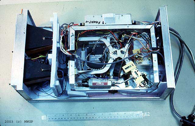
TMRS-2 19GHz Radiometer (JPG - 68K)
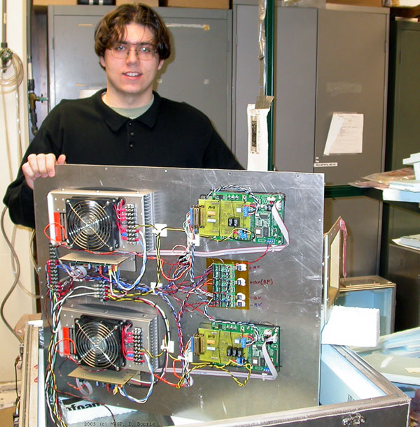
Below are pictures of the 19GHz and 37GHz radiometers, which are nearly identical, looking both down and up on the middle plates. From above, the RF Front end is visible while below, the large fan on the TEC along with the controllers are visible. These photos were taken before blue foam insulation had been added.
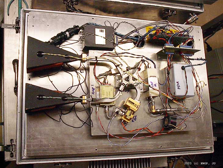
Top of 37GHz Radiometer (JPG - 109K)
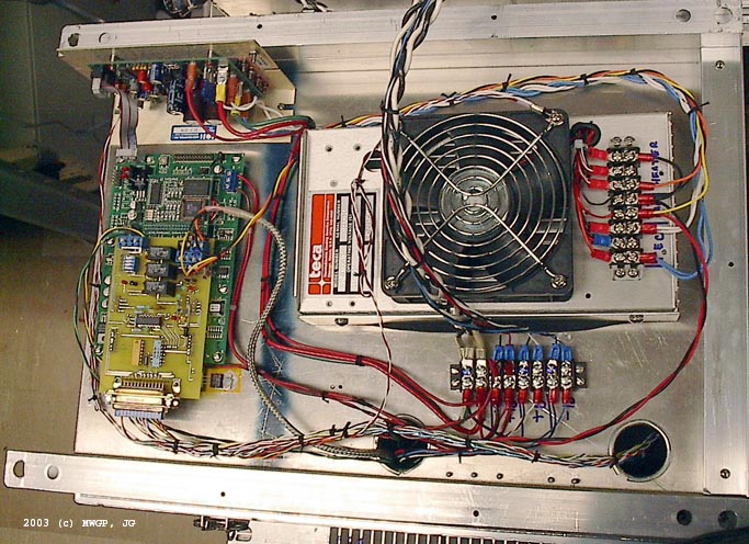
Bottom of 19GHz radiometer (JPG - 119K)
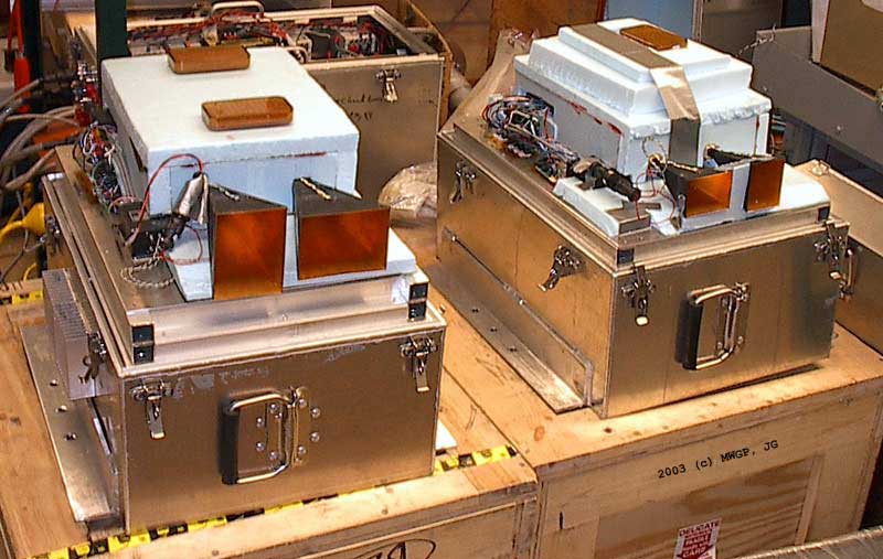
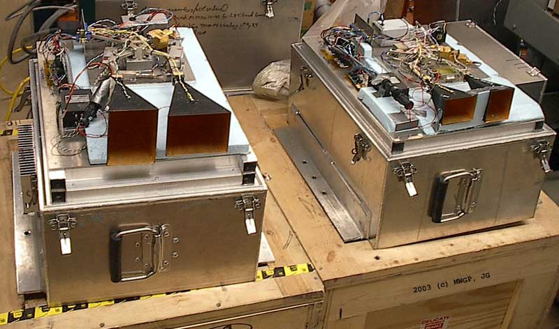
The following image sequence shows the completed 19GHz (left) and 37GHz (right) radiometers: 1) in their full cases with the antennas exposed, 2) With the top case off but the insulation over the RF front-end, and 3) with the RF plates exposed.
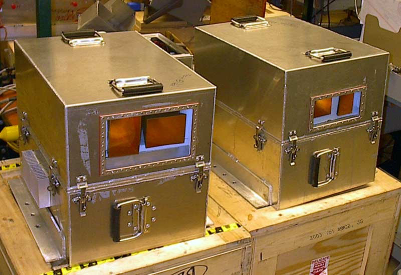 19 and 37 GHz Radiometers with cases on (JPG - 58K) |
 19 and 37 GHz Radiometers with cases off (JPG - 67K) |
 19 and 37 GHz Radiometers with cases and insulation off (JPG - 60K) |
|
C-band (6.9GHz) Radiometer
The C-band radiometer is the first radiometer built using the STAR-Light front end module. These pictures show some progression of the build and of the final system.

L-band (1.4GHz) Radiometer
The L-band radiometer has a slightly different construction layout than the others although it is almost functionally identical to the C-band. Because of the small environmental case, there was not room to put the Z-world microcontrollers below the middle mounting plate. Therefore, there are two mounting plates, and upper and a lower giving three chambers. The bottom chamber is still for the thermal system. The middle chamber houses the RF electronics which are mounted to the lower mouting plate with the TEC. The upper chamber houses the microcontroller and additional regulators mounted on the upper mounting plate.
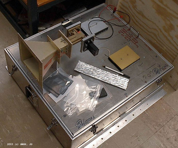
The first image shows a glancing view of the lower section of the L-band case. Within it can be seen the two mounting flanges, the cabling, and the orange case heater. Resting on the edge of the upper mounting flange is the lower mounting plate, which falls down into the case to create the lower chamber. The two TECs and thermal controllers can be seen on this plate.

L band bottom chamber (JPG - 102K)
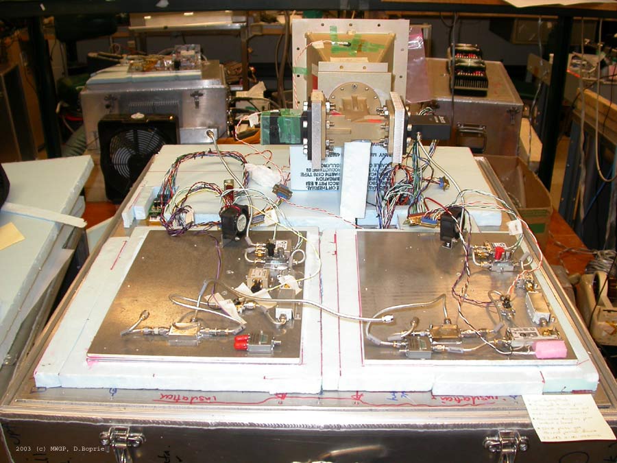
At the bottom of this next image, a top down view of the L-band case is shown with the lower mounting plate installed. On this plate from the top side, the two RF cold-plates with STAR-Light modules can be seen, along with some foil insulation, wiring and center mounted regulators. At the top of the image is the top of the upper mounting plate. The rest of the regulators and the two Z-world controllers are mounted here. When fully assembled, this plate is located directly on top of the lower mounting plate.
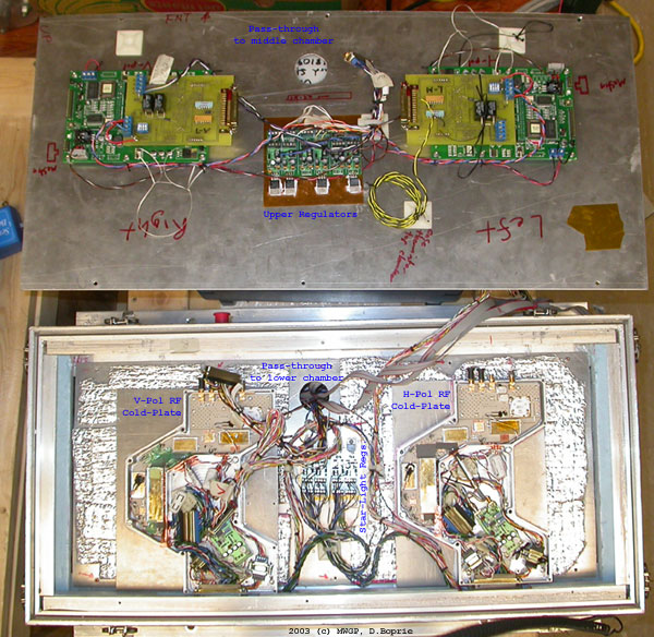
L band middle and upper chambers (JPG - 126K)
Power Supply Box
The power supply box holds the 10 regulated power supplies that run all four radiometer systems including a 24V 50A supply that runs all six of the TECs. On its side, it has a number of connectors to provide power and data distrabution to each radiometer box and the master controls at the bottom of the truck boom.
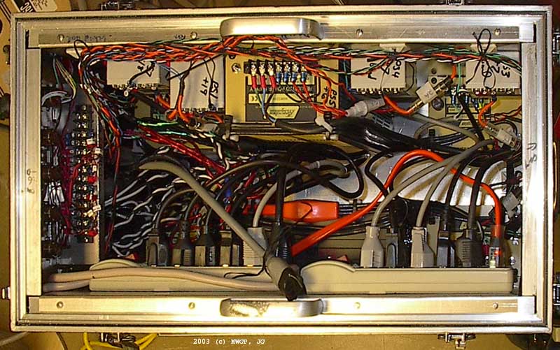 Power Supply Box Insides (JPG - 98K) |
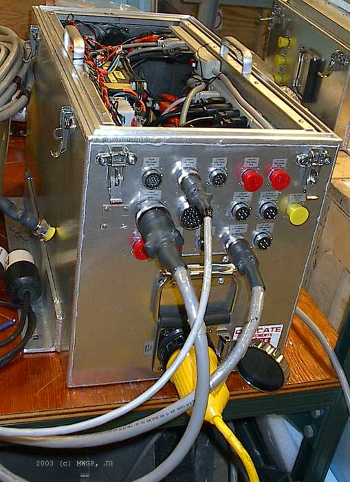 Power Supply Box Connectors (JPG - 65K) |