Thermal Control Subsystem
Overview
It is very important that the RF front-end electronics maintain a constant temperature with very little variation over both the long and short term. Slight variations in temperature affect both the gain and noise margin of the analog electronics. This correlates to degradation of scientific data. It is also important to keep the rest of the backend systems at a reasonable temperature but with little need for tight thermal control.
Diagram of Thermal System Layout
Case Control
In order to meet these two different scenarios, a two-layered approach was used. The radiometer casing is thermally coupled to the external environment with number of passive heat sinks. Internal baffles and fans direct the air over the heat sinks within the case and an external fan circulates ambient environmental air over the external heat sinks. The cases are also shielded from direct sunlight and wind with the use of space blankets. Also within the radiometer case are a number of resistive heaters in the lower chamber and on the antenna (not for L-band).
These heaters and fans are controlled directly by the Z-world microcontroller through a three SPST relays. Software on the Z-world performs rudimentary thermal control using simple dead-band control. This works simply by measuring the internal temperature and comparing it to a given set point. If it is below the set point, heaters are turned on and if it is above the set point external fan is turned on. Originally, the set point was just a temperature that was the same as the RF front-end. We found that the front-end control worked much better with a given temperature difference rather than an absolute temperature. The antenna and case heaters are controlled independently.
Front-End Control
The RF front-end electronics are mounted on a cold-plate and enclosed in a second layer of insulation. The cold-plate is coupled to a TECA AHP-300CPHC Thermo-Electric Cooler (TEC). This TEC is based on a peltier effect semiconductor device and can move heat from one side to the other proportional to the direction and strength of current moving through it. This model at maximum power draws 6.3A at 24V while moving about 80W of heat over a 10C thermal difference. The hot side is exposed to the inside of the radiometer case. Because the Z-world controls the case temperature nominally, the control of the TEC does not need to work as hard to maintain a stable temperature as it would if it was directly coupled to the outside environment. Of course, the terms "hot-side" and "cold-side" are only relatively arbitrary because the TEC is bi-directional but it usually used to cool.
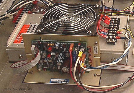
McShane Controller and TEC
In order to maintain such precise temperature stability of the cold-plate an independent proportional temperature controller is used. In this case an off the shelf controller from OVEN Industries was selected. This controller has a number of features that make it ideal for our use. It performs PID (Proportional-Integral-Derivative) control of the TEC using PWM (Pulse Width Modulation) for high efficiency and small size. Its control interface is over RS-232 serial and it has non-volatile memory. Most importantly it is has a temperature precision of 10mK. After properly tuning and settling, the variation is under 2mK RMS over a half-hour.
Graph of Performance - Coming Soon
Controller Issues
We had a number of issues dealing with OVEN controller sold through McShane Inc. The first issue was with the voltage range. The device was supposed to operate with up to a 24V supply at up to 10A. However, on first power-up, there was a small explosion of one of the power diodes. After some investigation, it turns out that engineering, manufacturing, and marketing didn't talk too well. They had installed a few parts that had a peak voltage limit of 5V, oops. Later, after some revisions, the maximum operating voltage was dropped to 20V and then later raised to 28V. The other major issue was the temperature range was limited to 0 to 30C. After more revisions and a lot of legwork on our part, the final controller (Part ENG-1455) has an extended temperature range -30C to 50C.
Thermal Limitations
After a season of field experiments in Frasier, Colorado, the limitations of the thermal system were characterized. Although the TEC can move up to 78W of heat in cooling mode, that depends on having a large differential between the hot and cold sides. Because the cooling of the case is passive through a large thermal resistance (i.e. the case heat sinks) the internal case temperature remains about 15C above the environmental temperature. This pushes the temperature of the RF cold-plate up limiting the dynamic range of the control system.
It would therefore be helpful to decrease the thermal resistance of the case to environment or actively push the heat out. This could be done by adding more heat sinks, increasing the airflow of the fans, or introducing water-cooling of the case. Active cooling could be implemented with a phase change system or with a secondary TEC module, but both of these add significant weight and power requirements.
Alternate Thermal Compensation
The L-band and C-band radiometers use the STAR-Light front-end. The STAR-Light front-end includes temperature-compensating attenuators that are selected to inversely match the temperature dependent gain of the amplifiers. Assuming that the temperature is constant across the circuit board (due to the massive copper and aluminum blocks) the attenuators will help to decrease the system temperature coefficient.
The other technique used on all the radiometers is comparison to a reference load that tracks the temperature of the receiver circuitry. Every measurement of the antennas is compared to a before and after measurement of the reference RF load kept at the same temperature as the electronics.