Microcontroller Back-end
Sections
- Requirements for Control
- Tasks
- Z-world Microcontroller
- Real-Time Tasks
- Memory Allocation
- Startup Functions
- Serial Command Interface
- Serial Interface to Thermal Controller
- Temperature Measurement
- RF Measurement and Burst Sampling
- Heater Thermal Control
Requirements for Control
Any radiometer other than the absolute minimalist one needs to be controlled. The old TMRS-2 used almost all custom components. It worked great in its time, but was very proprietary and ran using HyperCard on a Macintosh computer which was prone to failure. The more recent DSDR system used a single microcontroller board from Z-world as a brain, but still required a number of custom support electronics. Using a programmable microcontroller offered a number of benefits.
From these previous systems, it was determined that putting as much functionality in software as possible was the best approach, especially since these systems are not life-support critical. A number of requirements were made for the radiometers' local control systems:
- Full Autonomy for at least 24 hours
- Reliable & fault-tolerant operation
- Must monitor and control all functions of analog sampling
- Expandable/Extensible to STAR-Light digital sampling, other radiometers
- Communicate with a master control software on a PC
Tasks
Once the controller requirements had been outlined, it was important to draw up what tasks the control system would be responsible for.
- Control power-on/startup
- Recover from power-failure/errors
- Monitor temperatures
- Control temperatures
- Communicate with host
- Perform sampling of radiometer input
- Store data locally
- Keep track of errors
- Manage differences in radiometer types and styles
Z-world Microcontroller
The heart of each control system was to be a stand-alone embedded microcontroller that could be easily interfaced to the equipment and the host controller. A suitable controller, the Z-world Omega BL1720, was chosen for use. The BL1720 has a number of features that are desirable:
- Programming environment in modified C
- Royalty-free simplified Real-Time-Kernel (RTK)
- 18.4 MHz Z180 processor
- Watchdog timer; physical and virtual
- Real-time battery backed clock
- 2 serial ports; RS-232 3/5-wire & RS-485 2-wire
- 10 analog inputs; 8 op-amp buffered, 2 un-buffered
- 16 digital inputs
- 16 digital outputs; sinking
- 512kB of SRAM; windowed addressing, protected
- 128kB of FLASH
One of the big selling point was the programming environment and the Real-Time-Kernel. Using C allowed for easy programming without having to deal with assembly language. This makes future modifications and debugging much easier. A new user with some experience with C or C++ can jump into the code with little background. The RTK makes timing issues minimal and protects against errors. The BL1720 has a main processor module very similar to the one used in the DSDR system. Interestingly enough, the BL1720 was just recently put out to pasture by Z-world as it were in favor of more capable ethernet enabled microcontrollers. Because the code is in C, it is relatively portable to new architectures.
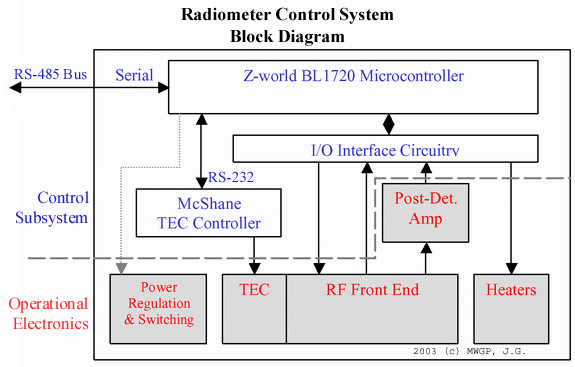
The BL1720 isn't a perfect drop in however. There are some external components that need to be used, an Input/Output Interface Board in order to connect the BL1720 with the devices in the radiometers. Furthermore, because of the importance of accurate temperature control for the RF electronics, a separate stand-alone TEC thermal controller is used. The general layout used for the TMRS-3 repack radiometers is shown below:
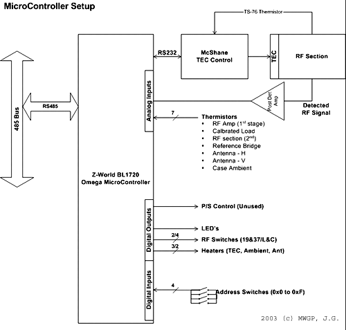
A more detailed connection diagram for the BL1720 is shown below:
Real-Time Tasks
The RTK of the BL1720 allows for priority based execution of functions. It also makes preemptive scheduling very easy to do. This is very important to make sure that all functions interoperate well, despite each working at a different rate. Having to program an operating system from scratch that was optimized would be very difficult and time consuming. The program code to run on the Z-world BL1720 is broken up into six real-time tasks and a background task:
- Burst sample of RF data to memory (BURST)
- Serial communications with master (CLI)
- Serial communications with thermal controller (MCSHN)
- Temperature Measurement (MEASTEMP)
- RF measurement processing and scheduling (RFMEAS)
- Ambient temperature control (TAMBCTRL)
Memory Allocation
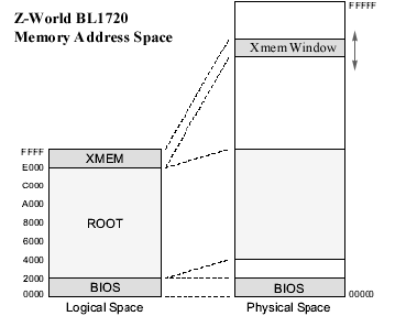
The Z180 uses a 16 bit internal address bus, but the BL1720 has a 20 bit address bus. This means that the Z180 can logically address 64KB of SRAM at one time, despite the 1MB width that the 20 bit address suggests. In order to access the full 512KB of SRAM, the top 8KB of the logical memory space is mapped to the rest of the physical memory space. This gets around the 16 bit addressing problem, but it makes use of the full memory space difficult. The only way to access the upper memory is to use "xmem" transfers that take time and are inefficient. This made some functions more difficult to write. Memory management was also made difficult because variables and code space occupy the base 64K of SRAM. If one section gets to large, it can collide with the other. Luckily the compiler warns of this and won't run the code, but it does put restrictions on code and variable size that just shouldn't be there for all the physical RAM that exists.
Z-world offers the capability to for protected memory. If power should fail, or the watchdog timer hits, data stored in memory could be destroyed or lost if the failure comes at a critical time. By defining variables in memory as protected, a four step process is implemented to make backups and checks of these variables upon all writes. The only variable for this application that is absolutely important to store is the number of processed data sets stored in the result table (int DB_Pnts).
Almost all functional variables in the microcontroller code were declared as global variables. Although this goes against good programming style, it was important to do in this case for two reasons. Global variables are much faster with this compiler because they are directly allocated in memory instead of put on the stack. That means less time is needed to access a global variable. Also, with the simplified kernel, there is no way to pass information between tasks without the use of globals because there is no message-passing capabilities of the RTK. Nonetheless, the variable space is well defined and read/write conflicts are minimized by the use of proper scheduling.
There are two major uses of the extended memory. One is to store a table of processed data sets. The protected variable DB_Pnts keeps track of how many valid data sets are in the table and control access to the table. Therefore, it is not necessary to protect the entire table. The other use of the extended memory is a 4x16000 float table that is used to store raw samples of the RF measurement data prior to processing during the burst sample function (BURST).
Startup Functions
There are a number of tasks that must be performed on startup before allowing the real time tasks to take over. The first step is to detect why the startup is occurring. Is it because the Z-world was just reprogrammed, or because of a power failure, or was it because of a watchdog timeout? Depending on the answer, the protected variables are recovered and an error is logged into the error stack. Then the digital inputs are checked for the address code. This allows the microcontroller to know which type of radiometer it is installed in, as well as know which serial address to use over the RS-485 bus.
At this point, the user can enable some temperature management options at compile time. Since the primary environment for these radiometers will be in arctic conditions, it is important to get the internal temperature above zero before powering up certain components. A coldstart function can be used to keep everything off and locked down until the temperature is in a safe zone.
Once everything is ready to go, the Real-Time-Kernel is invoked. Three real-time tasks are also scheduled: serial communication (CLI), temperature measurement (MEASTEMP), and ambient temperature control (TAMBCTRL). The main program then drops into an infinite loop that executes in the background between scheduled tasks at the lowest priority level. This is to prevent the main function from returning and possibly halting the program.
Serial Command Interface
The Serial Command Interface (CLI) is invoked once every second. It checks the RS-485 serial receive buffer for an end of transmission (ETX) character. If this character is present, it checks for a prefix that matches its address. If the destination address is wrong, the message is discarded. If the prefix matches the controller address, the command decoded using an if/else structure. Any required variables are parsed out, the message is checked for errors, and the requested task is performed. Then a reply is generated and entered into transmit buffer and the CLI function ends. The commands conform to the Radiometer Control Language (RadiCL) specification. Any errors generate a error code to go on the error stack.
Serial Interface to Thermal Controller
The Thermoelectric Cooler (TEC) controller is completely stand alone. However, it is necessary to keep track of its parameters, such as temperature, output level, and check for alarms. It is also desirable to update the PID coefficients and change the set point. The MCSHN communication function is called by either the serial command interface (CLI) or by the temperature measurement (MEASTEMP) function. In this case, the Z-world acts as the master and the TEC controller is the slave.
This function uses a global flag to make sure it is not called by any function when it is running. It is important to prevent conflicts. At the same time, if the TEC controller is not connected to the serial port or is not responding, an error is generated and added to the error stack and the function ends. Once running, this task converts the desired command and a parameter into the special format used by the TEC controller and sends it out on the RS-232 serial port. When the reply has been received, it decodes the reply and puts the return value into memory for the calling function to use.
Temperature Measurement
One of the most important functions in the radiometer is keeping track of temperatures. Therefore, temperature measurement is important to do correctly. The temperature measurement function's main task is to read temperatures from various thermisters. It uses a four step process to find the temperature of each thermister:
- Read n voltage measurements and average. Slightly increases statistical precision.
- Convert voltage to resistance. Uses ohms law equations of circuit.
- Decimated Search of R vs. T table for nearest value. Decimated search is faster.
- Linear interpolation of temperature.
An alternate method would be to calculate the temperature directly from the voltage using the characteristic equation of the thermister, but this requires more complex math functions that take magnitudes longer to calculate. Using the interpolated lookup table results in the required precision and is very fast. After measuring the thermisters, two calls are made to the MCSHN task to get the temperature and power output of the TEC Controller. Lastly, the variation in temperature from the last cycle is compared to give a rough estimate of the temperature status of the radiometer in general.
RF Measurement and Burst Sampling
The RF measurement system actually uses two real time tasks, RFMEAS and BURST. RFMEAS has a low priority and is involved in setting up a burst sample, processing the data, and storing the results. When called, RFMEAS checks to make sure that there is room left in the results table to store data. Then it begins by storing the temperature of the RF components. It switches to the first RF input, the reference load, and requests a high priority burst sample. Then it switches through and burst samples the two antenna inputs (or antenna and noise input) and finally the reference load again. It checks the temperature stability from the start of sampling to the end and makes sure the system is stable.
After completing all the sampling, the RFMEAS function calculates the first and second moment (mean and variance) of the data for each input. The mean is the time-integrated signal proportional to the radio brightness. The variance is used to check for statistical agreement and stability. It then throws out all the raw samples because they are not needed. A date/time stamp, four temperatures, and the mean and variance data comprise one completed data node. This data node is stored into the data table in memory, the protected DB_Pnts counter is incremented, and the function exits.
Because we are throwing away the raw data anyway, it would be nice to process the mean and variance on the fly and not store the data to begin with. However, this requires serious processor overhead and slows down the sampling function by nearly 10 times. As discussed above, root memory is at a premium so only a small number of samples can be stored at a time. The solution is to store raw samples into extended memory temporarily. This is the task of the BURST sample function.
The BURST sample task runs at the highest priority and cannot be interrupted except by watchdog timeout. It can be called to record anywhere from 1 to 16k samples. To overcome the root memory problem, it records 2k samples directly to root memory and then does a quick transfer into a 16kword extended memory block. This way the 2k samples fit within the extended memory window. The process repeats until the desired number of points have been recorded. The RFMEAS function then just has to copy the samples back into root memory for processing using the same memory space. Using this method, the average sample rate is approximately 2.2kHz over 16k samples. This is great compared to a continuous theoretical peak sample rate of 3kHz.
Heater Thermal Control
Because of the arctic conditions that the TMRS-3 radiometers will be operating in, maintaining a high enough temperature is as important as keeping the RF components at a stable temperature. Also, by controlling the ambient environment of the hot-side of the Thermoelectric Cooler (TEC), the TEC controller doesn't need to correct for variations on the heat rejection side and the system stability increases. A number of heaters are installed in the radiometers. One in the case on the hot-side of the TEC, one set on the antennas (except for L-band), and one on the TEC itself. The TEC heater would only be used for cold-start conditions and never with the TEC on. The antenna heaters are used to keep the antenna temperatures stable and near that of the RF components so there isn't a temperature gradient on the waveguide/coax.
The TAMBCTRL function uses dead band control for the heaters. As the temperature drops below the dead band around the set point, the requisite heater is turned on. When the temperature has risen above the dead band set point, the heater is turned off. The TAMBCTRL task is called only once every 20 seconds, but this is enough to get about one degree of variation in temperature using a very loose heater control system.