


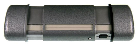
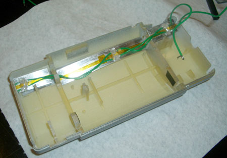
The clear lens for the EL lights were machined out of 1/8 inch thick, abrasion resistant polycarbonate to prevent the nicks and scratches that could occur with the constant handling of the scanner. A small lip was machined on the lens so that the pieces could be set into the slots on the body and glued from the inside. Three lens pieces were machined to fit the three sections of the scanner.
The EL lights also had to be cut into three segments to fit into the scanner.
1.
The plastic laminating material was removed from the back of the EL
tape to expose the electrodes.
2. Acetone was used to clean off the adhesive residue from the laminating
film. Care was taken not to wipe away the phosphor core in between the
electrodes.
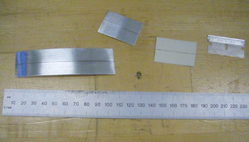
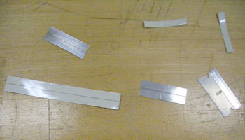
3. EL tape was cut to the desired width and length.
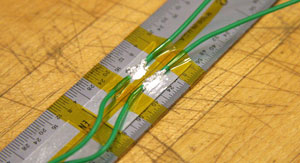
4. Electrical connections were made using conductive epoxy. Soldering
directly onto the electrodes ruins the phosphor core and causes unslightly
blotches in the EL lights. While the epoxy cures, a slight pressure
was placed at the connection point to ensure good contact.
5. Fast setting, 5 minute epoxy was used to insulate and reinforce the
connections.
6. Tape was placed on the electrodes to prevent exposing any high voltages
| Difficulties Encountered : |
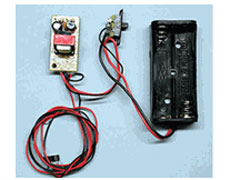
Even with the low profile and flexibility of the EL lights, we still encountered a packaging problem because of the power supply required to run the lights. The EL lights required 9 volts and a large inverter to run.
Alternatives:
To
solve these packaging problems there are a couple of solutions:
1. Use EL lights that require less power and a smaller inverter.
Source: http://www.e-clec-tech.com/elpowersupply.html
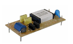
Source: http://www.e-clec-tech.com/inverterccft.html
2. Use bright surface mount LEDs and an opaque diffuser to provide a
uniform light and limit the range of the glow.
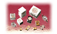
Source: http://www.marktechopto.com/Products/leds-drivers-displays-products-catalog.cfm