


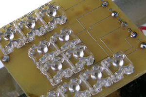
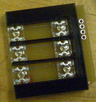
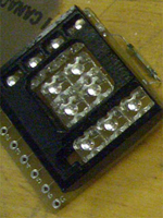
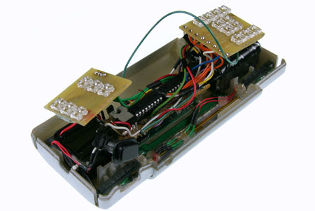
In order to create the displays, we used 4 layers. The bottom layer is the PCB that was printed at ExpressPCB.com and color LED’s were soldered on them. These LED’s were obtained from superbrightleds.com. We used surface mount resistors to get a low profile for the PCB. A black acrylic cutout corresponding to the symbols was placed on top of the LED’s. These cutouts were made using a laser cutter. These cutouts block the LED’s from lighting up the wrong symbols. A transparency is printed with the desired symbol and is placed on top of this. Between the LED’s and the transparency we placed a piece of silicone this was used to diffuse the light so that the symbol lighting looked diffuse. A piece of abrasion resistant polycarbonate was placed on top of this and this assembly is fitted inside the body of the scanner.
| Problems with current design and Improvements: |
The
current design had a very thick profile and it was problematic to get
it to fit into the small volume present in the device. Instead of using
LED’s obtained from super bright LED’s it would be better
to go with low profile surface mount LED’s with the appropriate
brightness. Also instead of silicone we could use diffusing paper that
would make the LED’s look more diffuse. Instead of a flashing battery
sign for the guide, we should have a beeper to indicate that the four
critical clues have been found.