


Electronic implementation was mainly software implementation – a man, a fishbowl, and an awful lot of assembly code (see the “design” pages)
Electronic hardware implementation is as follows:
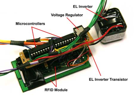
Here we can see the bench layout of the major internal components – the RFID module sat underneath the main board, with the inverter to the right and connections for the two display panels and USB connector going off the picture.
The main board holds two microcontrollers mounted in sockets, a voltage regulator take the ~7.2V from the battery pack (not shown) to a steady 5V, a crystal oscillator mounted underneath the voltage regulator and the transistor to drive the EL lighting inverter. Not visible are pull-up and pull-down resistors and the diode across the terminals of the EL inverter, which are mounted to the underside of the board. The assembly is build on veroboard and soldered by hand.
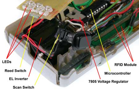
This picture shows the same components mounted inside the cluescanner body. Components are held in place by posts locating in holes in the boards and secured with hot-glue.
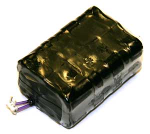
The battery pack is made from 6 NiMH ‘AAA’ cells. The cells are designed for high capacity at slow-discharge rates, and come equipped with ‘tags’ so that you can solder them together without damaging the cells themselves. Insulation tape and heat-shrink sleeve keep the pack together and prevent shorts.
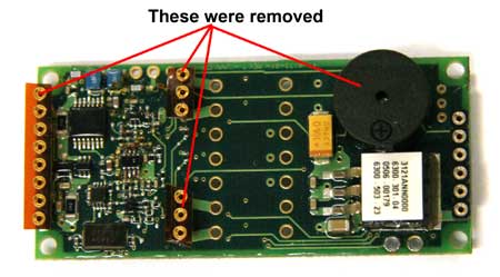
The RFID module itself was modified by removing the buzzer and header pins – this reduced the height of the module significantly and allowed for tighter packaging.
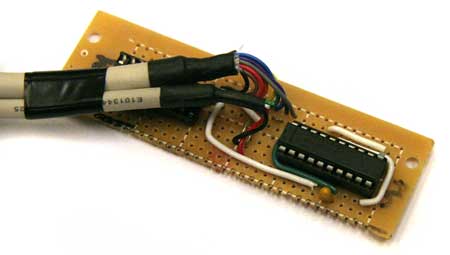
On the computer-link side of things, this is a simple logic to RS232 converter. Logic ‘0’ is represented by 0V and logic ‘1’ is represented by +5V. RS232 ‘0’ is represented by -13V and RS232 ‘1’ is represented by +13V. The MAX232 chip show converts between these voltages. The thinner cable to the left comes from the scanner USB ports and the thicker cable goes to the PC serial port.
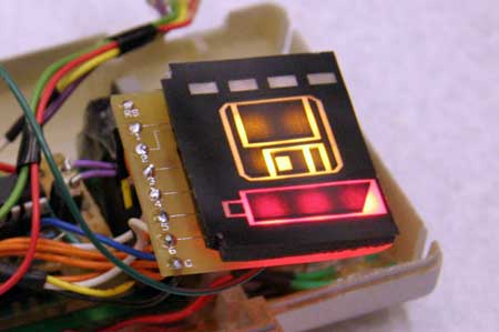
This is a shot of the displays before the LEDs were attached with a grinder due to packaging problems – note how bright the displays are and the difficulty we had diffusing the light.
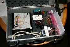
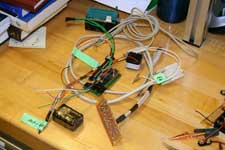
Two photos of the “2.744 Geek-Kit” – enough to rival any course 6 class…
| Downloading Data from the Scanner: |
| The easiest way to get data from the scanner is to use a serial RS232 signal. The Pic micro controller transmits an RS232 signal that includes the tag numbers recorded from the RFID reader. The RS232 signal is text data that we can read through the serial port of the computer. Reading an RS232 signal can be done using many different compilers available. The most basic protocol is to use a HyperTerminal attached to the COM port. This does not let you do anything except read the raw serial data. We used this primarily to test and debug our code. |  |
We decided to use Visual Studio .NET to download the data and store it to a text file. We used a class generated by Corrado Cavalli and available at http://www.codeworks.it/net/VBNetRs232.htm. The class can initialize the COM port, read and write serial data. The code that we wrote reads the RS232 signal, picks out the relevant information, writes it to a file and displays corresponding images. Once the text data is read it can be split up and sorted into its corresponding images.
| Screenshots from the Software: |
This is the design of the visual basic interface that we designed to convey the user experience. To see it in action, visit In Action under the User Experience link.
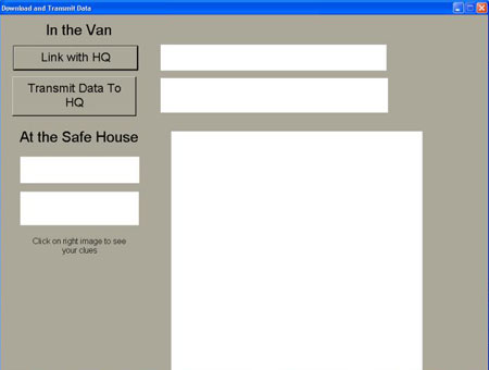
Once the
scanner is connected to the dock, the Link with HQ button opens the
COM port for communication.
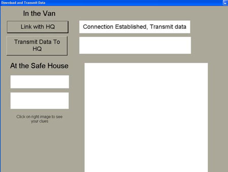
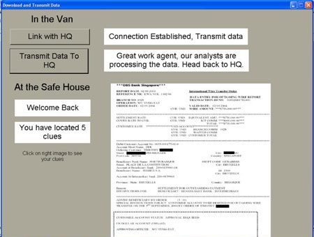
The Transmit Data to HQ button reads the RS232 signal and tells the
user what they have found and displays the corresponding images.
A sample copy of the code I wrote can be found here:
| Suggested Improvements : |
It is not necessary to use visual studio to read the serial data, any compiler will have code to do this. All that needs to be done is for the code to read the text data coming from the PIC and sort it into the relevant clues and then write this information to a text file. The text file can be read by and software (like flash) which can then play a video of the corresponding result. We recommend that all the post processing to be done using the software and have the PIC transmit as much raw data as possible.