


| Our System - Microcontroller: |
The microcontroller we chose was the PIC 16F88. It’s fast enough to do everything that we need, it can drive LEDs directly and the software development environment is free. The microcontrollers and programming equipment are inexpensive ($3 and $70), the chips themselves are virtually impossible to destroy and there’s acres of source-code and incredibly helpful hobbyists out there. The latter two were extremely important given that our team are all mechanical engineers with only basic electronics skills and zero microcontroller programming experience! Click the links for more information about Microchip, PIC Microcontrollers, and the 16F88.
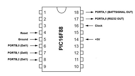
There are actually two microcontrollers in the device because of the number of inputs and outputs we needed. I’ll start with the “lighting” microcontroller layout:

The important connections for the PIC are Ground, +5V, Clock and Reset. Ground and +5V power the device and provide a voltage reference for all signals. The reset pin is normally held high by a 1k ohm resistor, but can be pulled low via a switch between the Reset pin and Ground to reset the device. The Clock input is connected to the output from a 4Mhz crystal oscillator circuit. We chose the self-contained oscillator package rather than a crystal and two capacitors because it’s guaranteed to work off the shelf and frees up an extra port (PORTA,6). We chose 4Mhz because the PIC divides the frequency down 4 times – a 4Mhz clock means a 1Mhz chip, a 1Mhz chip means each instruction takes 1 microsecond and multiplies of 1 microsecond are convenient to work with when using timed loops.
BATTSIGNAL, SCANSIGNAL and REEDSIGNAL are inputs. If BATTSIGNAL is high then we know we should initiate the battery light routine if we’ve not done so already. If SCANSIGNAL is high then we know we should initiate the scanning sequence if we’ve not done so already. If REEDSIGNAL is high then we know the case is open and we should turn the symbol lights on. 1k ohm pull-down resistors ensure that these ports are normally held low.
Every other port is an output connected to an LED – PAPER1/PAPER2/PAPER3 for the scanning instruction symbol; SCAN1/SCAN2/SCAN3/SCAN4 for the scanning instruction symbol; DISK for the disk symbol and BATT for the battery symbol.
The code is long-winded and looks best when viewed in MPLAB. To do this, download MPLAB from here and download the commented code here. The comments explain how it works in detail, but in essence it asks itself what part of the sequence it’s currently in, what inputs it’s got, sets some lights, waits for a multiple of 150 milliseconds then goes back to ask itself what part of the sequence it’s currently in, what inputs it’s got, sets some lights and so forth. The Disk routine and Battery routine do not respond to any inputs once they’ve been started – this is so that the user has to wait long enough for the RFID reader to reset itself and so that the user can’t fail to notice the low battery warning.
The RFID module -> Memory -> RS232 microcontroller is a little different:
Much simpler on the wiring front but more complex code. Same Ground, +5V, Clock and Reset as the lighting microcontroller. Commented code is here.
What this code does is sets up 96 memory addresses in memory bank 2 to be used as RFID tag storage bins, then broadcasts the contents of these storage bins, in sequence, via PORTA,0 as a 9600 Baud RS232 signal with no parity. (8N1 format). It’ll also check the status of a ‘cluesfound’ flag (which is set when we find the four critical clues) and turn on the BATTSIGNAL pin if that flag is set. It does this continually.
The way the microcontroller reads in tag IDs is through an “interrupt” function on PORTB. An interrupt makes the programme jump from whatever it was doing to the interrupt routine whenever something happens on a particular pin. In this case, as soon as the device sees an input on PORTB,0 it jumps to the interrupt routine, which reads PORTB, checks to see if we got a ‘0’, a ‘1’ or ‘nothing’ then, depending on the result, either puts a 0 in the carry bit, puts a 1 in the carry bit, or goes back and reads the port again to see if we’ve got anything this time.
Putting a 0 or 1 in the carry bit is followed by a “rotate” function. The best way to describe this to MechE students I’ve found is bears on a bed: Take your ‘carry’ bear, and roll it onto the righthand side of the bed. Keep doing this and eventually the bed will be full (8 bears). Keep doing this for all 26 bits, and what will happen is you end up with the last 8 bears on the bed and the other 18 bears lying on the floor. Those last 8 bears (bits) are the ones we are interested in! When we’ve finished bear-rolling, we take the bed and put it on a rack in a dorm-room (the dorm room having 96 beds). The program can also check whether those bears were VIPs and let roomservice know (ie – were they a critical clue) by comparing their ID number to the guestlist (a list of critical clue IDs pre-programmed in)
That’s essentially what the interrupt routine does – takes in serial data, stacks it into a register, checks to see whether the data was anything special (and sets a flag if it was) then files that register away in a 96 byte data-bank. For our demonstration code, we just took the first four IDs we saw as the four critical ones and set the flag when the cluecounter/file-location register hit four.
The RS232 routine is a “bit-banging” routine, in that there’s absolutely no handshaking or error correction whatsoever. What we do here is almost the opposite of the weigand routine – take the data to be transmitted and load blank bears onto the lefthand side of the bed. Each time you do it, the bear you wanted to transmit falls off the righthand side and you can set the output pin high/low as appropriate, wait the right amount of time for the 9600 baud rate, then do it again and again. Add a start and stop bit and you’re there!
| Our System - Everything Else!: |
The scanner connects to the computer through what looks like a USB port, but its not. It actually uses RS232 (serial port), but we chose to use USB plugs because it looks more modern, is physically smaller and easier to plug and unplug.
The four connections are ground, battery, data and reset. Ground and data are connected to the computer’s serial port via a MAX232 adapter circuit. Ground and battery go to a normal NiMH battery charger. Ground and reset go to a reset switch used to erase the memory on the device.
The internal circuitry is fabricated using a mixture of veroboard (main board) and printed circuit boards (LED boards) – in production versions this would be one PCB.
EL lighting cannot be driven from the microcontrollers due to the current draw. Instead, the EL lighting is driven by a 3904 general purpose NPN transistor with its emitter grounded, its collector connected to the ground of the EL lighting inverter and its base connected to the resistor in series with the scanning lights. This ensures that the EL lighting is powered whenever the scanning LEDs are – without using up an additional microcontroller output or logic circuitry. A diode across the terminals of the EL lighting inverter protects the rest of the device from back-emf when the EL lighting is switched off.
A ZIP file containing MPLAB, all source code, technical documentation from HID corp and Microchip can be found here.