


In the closed state (shown below) the scanner looks like a normal flip case. The user would naturally press the latch button to open the “eyeglass case.”
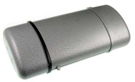
When the latch button is pressed, the two end caps pop out to reveal the scan button on the front and a data/power port on the back.
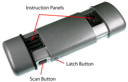
The reed switch is mounted at a fixed portion in the scanner while the magnet is mounted on one of the sliding parts. When the magnet gets close to the reed switch, it is triggered ON. This switch is used to turn on LEDs for the instructional panel on the left.
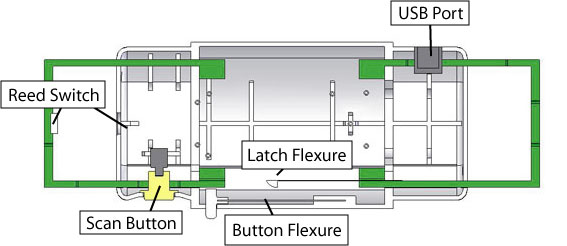
The latch button is mounted via the button flexure to the scanner case. The flexure provides the restoring force for the button to bring it back to its original state.
When the latch button is pressed with the scanner in the closed state, it pushes on the tip of the latch flexure that holds the two green sliding pieces together. Springs are connected between the connection points (four springs in total) add value of spring constant here on the case and the sliding pieces.
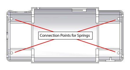
When the scanner is closed, the springs are in tension. As the latch flexure tip is pushed out of the slot, the sliding pieces retract and the tip of the latch flexure rides on the surface of the sliding part (see picture below). The scanner can be closed by pushing the two end caps together. As the scanner is closed, the latch flexure rides up onto the sliding piece and continues to ride along it, until it falls into the slot.
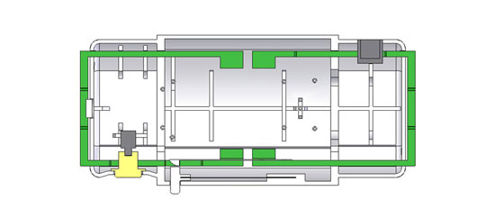
(Roll over image to see sliders open and close.)