


Radio frequency identification (RFID) is a technology used to identify objects. It’s non-contact, it doesn’t require any audio/visual signals or special alignment and the ID tag that goes on the object is small and inexpensive.
You’ve almost certainly been exposed to RFID before as it’s commonly used on clothing, CDs and library books to prevent unauthorised removal. How does it work? Depends on the type of system! We use passive tags, and in the words of Wikipedia:
“Passive RFID tags have no internal power supply. The minute electrical current induced in the antenna by the incoming radio frequency signal provides just enough power for the CMOS integrated circuit (IC) in the tag to power up and transmit a response.”
Click here for more information about the technology.
| Our System - Overview: |

Our system is designed to memorise the ID numbers of all the clues that the users scan in, and then transmit it to the exhibit control system in a way that’s easy to interpret.
Bringing an RFID tag with about 40mm of the RFID reader module will make it read the tag and output the ID number in ‘weigand’ format.
A microcontroller memorises this ID number as well as running all the switches, symbols and lighting on the device.
The microcontroller then sends the ID numbers as ASCII text over an RS232 link - a format that computers find it easier to understand beacuse they think they’re connected to a keyboard!
The computer reads this text and saves it to a file and from there it is very easy to “play the you saved the world sequence if you’ve found clues A, C and D” for example.
| Our System - Weigand Data: |
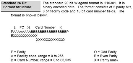
This standard gives up to 16,711,425 unique IDs. We don’t need this many and that number is awkward to handle, so what we do is read them all then discard all but the last 8 bits – you’ll see why this works well when we describe the code. The following excerpt from the user-manual for out particular scanner describes the actual data itself:
The wiegand output port is a two wire serial interface where logic 0 data bits are transmitted on the “Data 0” wire and logic 1 data bits are transmitted on the “Data 1” wire. The following diagram gives an example of a wiegand transmission using factory default settings.

When
no data is being transmitted the outputs are high (5V). Data bits are
represented by low-going pulses, with an interval of time between each
pulse. In the factory default configuration, the pulse width is 40us and
the spacing between pulses is 2ms. Pulse width is configurable in 4us
intervals with values ranging between 4us and 1.02ms. Pulse spacing is
configurable in 25us intervals with values ranging between 25us and 6.375ms.
Specifications for the wiegand communication protocol are detailed in
the Security Industry Association document SIA AC-01 (1996.10), Wiegand
Card Reader Interface Standard.
| Our System - RFID Module: |
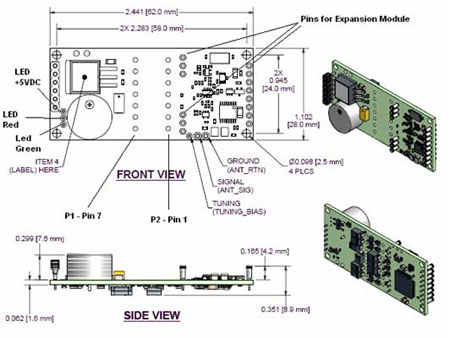
The module we chose was HIDCorp’s OEM150. HIDCorp because COO Steve Wagner generously agreed to support the 2.744 class with free RFID tags/modules/technical support; the OEM150 because it offered the combination of physical size, range and functionality. (The device needs just power and ground for it to read tags and output their IDs) The important details are listed below:
*Size: 83x38x10mm
Note: This is after we removed audio functionality and header pins
*Range: 40mm
Note: Less than 40mm range and there’s a danger than the scanner
might miss the clue if not held right on top of it; greater than 40mm
range and you might accidentally pick up a clue that the user hadn’t
intended to scan
*Current requirements: 52/80mA average/peak
*Voltage
requirements: 5-16V DC
Note: Linear (non-switching) power supply required
*Regulatory approval: Technically this is required
*Start-up
time: 3 seconds
Note: This means that we cannot power-down the device between scans, as
it’ll take so long to start back up again once the scan button is
pressed that either we’d have missed the tag by the time the device
is ready to read it or the user would get confused/fed up with a “warm-up
light” designed to delay them.
*Delay between
scans: 1-2 seconds
Note: When a tag is brought within range of the device, it will read it
and output the ID number once. It will not do anything else until that
tag has been moved out of range for 1-2 seconds. This is why the “flashing
disk” delay routine is as long as it is.
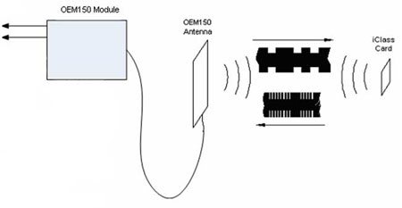
Some more
detail on how the tags work:
Polling of a transponder involves generating a 13.56MHz signal, referred
to as the carrier, at the input of the reader antenna. The input from
the reader antenna is transmitted in the form of magnetic fields. The
magnetic field generates a voltage across the card antenna. When this
voltage reaches a sufficient magnitude, the chip on the card will power
up and begin communicating with the reader by modulating the load impedance
seen by its antenna. The changing impedance on the card changes the mutual
inductance between the antennas, which in turn causes a change in the
magnitude of the exciter signal that drives the reader antenna. This change
in the exciter signal causes the receiver to attempt a read a response
driven by the credential.